Radiative heat transfer between two dielectric nanogratings in the scattering approach
Abstract
We present a theoretical study of radiative heat transfer between dielectric nanogratings in the scattering approach. As a comparision with these exact results, we also evaluate the domain of validity of Derjaguin’s Proximity Approximation (PA). We consider a system of two corrugated silica plates with various grating geometries, separation distances, and lateral displacement of the plates with respect to one another. Numerical computations show that while the PA is a good approximation for aligned gratings, it cannot be used when the gratings are laterally displaced. We illustrate this by a thermal modulator device for nanosystems based on such a displacement.
pacs
44.40.+a, 41.20.Jb, 73.20.MfRecent experiments and theoretical work have given promising perspectives in the field of radiative heat transfer in the micrometer range [1, 2, 3]. It has been shown that radiative heat transfer greatly exceeds the black body limit for distances shorter than the average thermal wavelength, which is understood as an effect arising from the contribution of the evanescent waves. The studies of near-field heat transfer are of great interest to the design of both NEMS and MEMS which are naturally affected by possible side-effects of heat exchange at the nanoscale. Other potential applications lie in the fields of nanotechnology, photonic crystals [4], metamaterials [5, 6], thermalphotovoltaics [7, 8], multilayered structures [9], improved resolution in nano-structure imaging, and new nano-fabrication techniques.
While radiative heat transfer beyond Stefan-Boltzmann’s law was observed experimentally [10] and described theoretically [11] over forty years ago, radiative heat transfer between two parallel flat plates at the nanoscale has been considered experimentally only recently [12, 13, 14]. The most interesting features of this field are the possible side-effects of non-trivial geometries on the thermal emission of nano-objects. Thus an in-depth study of heat transfer for different configurations has been performed over the years, ranging from the case of a particle facing a surface [15, 16, 17, 18], to particles or nanospheres facing each other [19, 20, 21, 22, 23], or more recently to the sphere-plane geometry [2, 24]. One should also note that for nearly flat surfaces where roughness is considered as a perturbation factor, certain perturbative approaches can be used [25, 26, 27]. But for larger geometrical irregularities, more accurate methods become necessary [28]. These more complex geometries are best described through a scattering approach [29, 30, 24, 31]. Another exciting perspective is the study of the variation in heat transfer brought forth by surface polaritons in certain materials [18]. In this paper we focus on the interplay between the surface waves excitation and the surface profile, as shown in Fig.1.
The fact that the radiative heat transfer in near-field considerably changes with variation of the separation distance between plane surfaces has already been shown [1, 2, 32]. When introducing a profile for the interfaces, the flux is expected to depend on the relative lateral displacement of the two surfaces denoted , as seen in Fig.1.

This is all the most interesting as a simple argument based on the Proximity Approximation suggests a strong modulation of the flux. Indeed, by assuming that one can use locally the plane-plane heat transfer coefficient, it is seen that the flux is maximum for . The validity of the proximity approximation has been discussed in the context of a plane-sphere [2] and between two spheres [19, 20]. While it appears to be valid for radius of curvatures larger than m, this validity in the context of lamellar gratings with sub-wavelength periods remains an open question. Here, we investigate this issue by using the exact formalism of scattering theory. Furthermore, we discuss the physical phenomena involved and show that the nature of the material needs to be taken into account when discussing the validity of the Proximity Approximation.
Based on the scattering formalism developed in [29], we consider two corrugated profiles at temperatures and , as shown in Fig.1. The heat transfer is constructed from the statistical average of the sum over the component of the Poynting vector and is thus related to a flux. We define the wave vector with defined with .
Following [33], we then introduce the reflection operators and of the two gratings separated by a distance , by which we understand the distance of closest approach, equal to zero at contact. We then set our scattering operators such that and . According to the scattering formalism for gratings developed in [33, 34], the scattering matrices are of dimensions , where is the order of diffraction.
We now define the operators as constructed from the projectors on the propagative and evanescent sectors, respectively :
| (1) | |||
| (2) |
where represents the transverse electric and transverse magnetic polarizations, respectively. The thermal energy density per field mode at temperature writes . We can now express the heat transfer coefficient between two gratings of same corrugation depths as :
| (3) |
with
| (4) | |||
| (5) | |||
| (6) | |||
| (7) |
It is noteworthy that the heat transfer depends on the shape and material properties of the gratings only through their scattering matrices and . Furthermore, the factor introduces a cut-off for all frequencies larger than . It is hence in equation (4), which corresponds to the sum of the transmission factors of the modes, that gives rise to the interesting modes pertaining to the near-field contribution.
Note also that the first perpendicular wave vector component belongs to the first Brillouin zone between and , whereas is not restricted. A practical challenge of the numerical integration of lays in the choice of the boundaries of and through a careful study of the integrand of equation (4) plotted over the whole range of frequencies to determine the modes.
We will from now on consider two gratings of silica glass SiO2, the dielectric properties of which are given in [35]. This material is chosen as it supports surface phonon-polaritons, which are known to enhance the flux. The gratings temperatures are supposed to be K and K. Two sets of data are systematically computed : the first corresponds to zero lateral displacement of the two plates along the -axis () so that the corrugation maxima directly face those from the opposite profile. The second corresponds to a lateral displacement of half the grating period (), so that the corrugations maxima face the corrugation trenches of the opposite profile. In near-field, the two structured plates expose a larger surface to each other at than at , so that we expect a strong modulation of the heat transfer coefficient which will be discussed later. This is based on the assumption that the plane-plane heat transfer coefficient is locally valid.
The results of the scattering approach can be compared with the PA, which consists on the weighted sum of the planar normal contributions depending on the local separation distances within each period. Assuming that , we have for :
| (8) | |||||
For , we find the following saturation value of :
| (9) | |||||
In what follows, we study in detail the interplay between surface waves and corrugations. In particular, we assess the validity of the PA. Fig.2 shows the heat transfer coefficient for and , as a function of the separation distance , for two gratings of period nm, filling factor , and groove depth nm. The results are compared with the PA. Regardless of the distance, we can see that the PA is a good approximation to the heat transfer coefficient at , but not at . At nm, the error of the PA is of for , and of for .
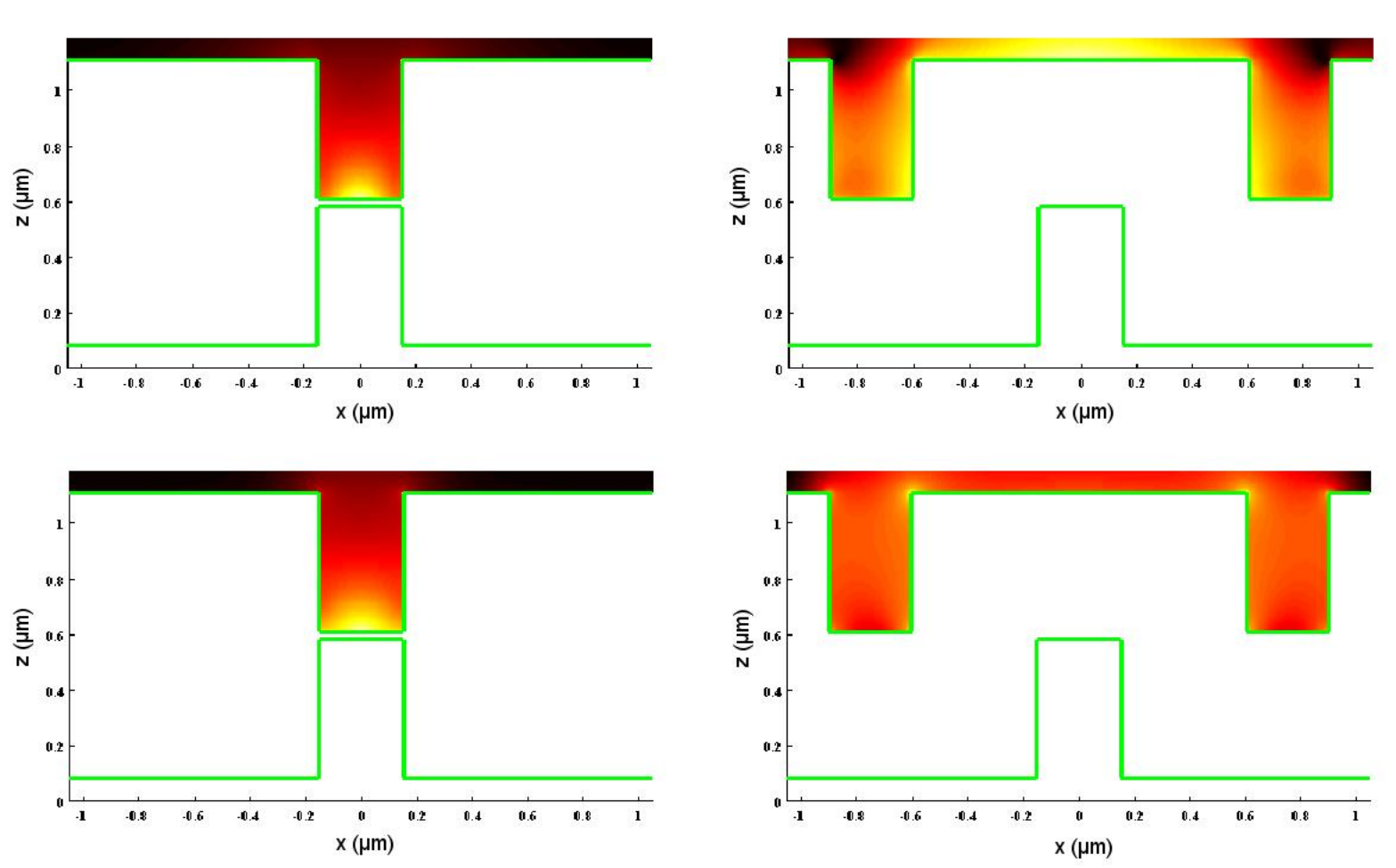
The reason for this is illustrated on Fig.3, which shows the field modulus map for a given source dipole that is placed in the middle of a corrugation right under the surface, and which is oriented perpendicular to it. The color scale is logarithmic. The intensity or square modulus of the electric field is represented only in the upper grating so as to highlight the place of absorption. The gratings have a separation distance nm, corrugation depth nm, period nm, and filling factor . Two different wavelengths m and m are considered, knowing that SiO2 has two resonance frequencies at m and m. In the case where and m, we see that the field is clearly both intense and confined. As m corresponds to the horizontal asymptote of the surface phonon dispersion relation, a large number of modes with different values of the wave vector are excited. This leads to a highly localized subwavelength hot spot. At m, the spot is broader as expected : this is similar to the loss of resolution of surperlens away from the resonance. On the right column of the figure, we show the intensity for . It is seen that the heated region is delocalized so that PA is clearly not valid. In this regime, the heat transfer is no longer due to a dipole-dipole interaction through the gap. Instead, a dipole excites modes of the structures. In turn, these spatially extended modes produce dissipation in the walls. This discussion indicates that PA is valid if the gap width does not vary significantly on a length scale given by the spatial extension of the modes.
To further illustrate this qualitative dependence of the radiative heat transfer on separation distance, we show in Fig.4 the heat transfer coefficients as a function of the separation distance between two plates of SiO2. One can distinguish three domains , , and , corresponding respectively to the extreme near-field below nm, to the near-field from nm to m, and to the domain of Stefan–Boltzmann’s law beyond m. The heat transfer coefficient changes in slope along these three ranges: the strongest contributions come respectively from the dipole-dipole interaction, from surface phonon-polaritons, and from the classical radiative heat transfer. The contribution in the first domain corresponds to the localized heat transfer seen in the upper-left map of Fig.3, whereas the main contribution in the second domain corresponds to the delocalized heat transfer mediated by the surface wave seen on the right maps of Fig.3.
It is also instructive to study the heat transfer modulation as a function of the corrugation period , as shown in Fig.5. We have selected six types of gratings with corrugation periods ranging from to nm, each with a groove depth nm and filling factor still fixed at . The separation distance is nm. The fact that the heat transfer coefficients at does not vary much with a change of period is a further confirmation of the validity of the PA in this configuration. At , however the scattering and PA results radically differ for small periods, but tend to agree for large periods. The reason for this is that when , the ratio tends to zero and we expect the heat transfer to be well approximated by the plane-plane case, and hence the PA.
Let us finally turn to the discussion of the modulation effect. Fig.2 shows that the heat transfer depends dramatically on the lateral displacement of the two surfaces, opening the possibility of a strong modulation via only lateral displacement of one of the two plates at a fixed distance. To assess the possible performance of such a system as a thermal modulator , we investigate the modulation factor for different filling factors. The results are illustrated in Fig.6 for gratings with a period and groove depth nm, and a separation distance nm. For these large separations, the modulation factor still reaches a maximum of about , at a filling factor corresponding to of the total grating period. At short distances (nm) it can reach up to 35 (c.f. Fig.2.).
So based on a - to our knowledge first - study of radiative heat transfer for corrugated dielectric plates - we have clarified the origin of the success and failure of the PA by analyzing the interplay between surface waves resonances and corrugations. we have shown for various nanograting geometries and separation distances that Derjaguin’s Proximity Approximation is clearly valid for but fails for . The key to the understanding of the system is the comparison of the lateral length scale of the surface corrugation with the lateral extension of surface waves involved in the heat transfer. Finally, we have narrowed down the optimum geometrical parameters of a thermal modulator device for nanosystems based on a lateral displacement of two corrugated plates facing each other at fixed distance. We found in general a stronger modulation for small filling factors and separation distances, and for large grating periods. In certain regimes it is possible to reach a modulation factor of more than . An in-depth study of the modes accounting for the most important part of the heat transfer would be an interesting prospect as well as to further enhance the modulation by using a broader range of materials [36] such as different alloys combining the polaritons of certain dielectrics and the near-field properties of metals. The issue of heat transfer in near-field in the case of coatings [9], phase change materials [32, 36], metamaterials [37, 6], or graphene-covered dielectrics [3] in this regard should also be explored.
The authors thank the ESF Research Networking Programme CASIMIR (www.casimir-network.com) for providing excellent possibilities for discussions and exchange. The research described here has been supported by Triangle de la Physique contract EIEM 2010-037T.
References
- [1] S.-A. Biehs and J.-J. Greffet, Phys. Rev. B 82, 245410 (2010).
- [2] C. Otey and S. Fan, Phys. Rev. B 84, 245431 (2011).
- [3] V. B. Svetovoy, P. J. van Zwol, and J. Chevrier, arXiv:1201.1824v1 (2012).
- [4] P. Ben-Abdallah, K. Joulain, and A. Pryamikov, Appl. Phys. Lett. 96, 143117 (2010).
- [5] K. Joulain, P. Ben-Abdallah, and J. Drevillon, Phys. Rev. B 81, 165119 (2010).
- [6] M. Francoeur, S. Basu, and S. Petersen, Optics Exp. 19(20), 18774 (2011).
- [7] K. Park, S. Basu, W. P. King, and Z. M. Zhang, J. of Quant. Spec. and Rad. Trans. 109, 305 (2008).
- [8] M. Laroche, R. Carminati, and J. Greffet, J. of Quant. Spec. and Rad. Trans. 100, 063704 (2006).
- [9] S.-A. Biehs, Eur. Phys. J. B 58, 423 (2007).
- [10] C. M. Hargreaves, Phys. Lett. 30 A, 491–492 (1969).
- [11] D. Polder and M. V. Hove, Phys. Rev. B 4, 3303 (1971).
- [12] A. I. Volokitin and B. N. J. Persson, Phys. Rev. B 78, 155437 (2008).
- [13] E. Rousseau, A. Siria, G. Jourdan, S. Volz, F. Comin, J. Chevrier, and J.-J. Greffet, Nature Photonics 3, 514 (2009).
- [14] S. Shen, A. Narayanaswamy, and G. C. Nano, Nano Lett. 9, 2909–2913 (2009).
- [15] S. Y. Buhmann and S. Scheel, Phys. Rev. Lett. 100, 253201 (2008).
- [16] O. Huth, F. Rüting, S.-A. Biehs, and M. Holthaus, Eur. Phys. J. Appl. Phys. 50, 10603 (2010).
- [17] M. Antezza, L. Pitaevskii, S. Stringari, and V. Svetovoy, Phys. Rev. A 77, 022901 (2008).
- [18] J.-P. Mulet, K. Joulain, R. Carminati, and J.-J. Greffet, Appl. Phys. Lett. 78, 2931 (2001).
- [19] A. Narayanaswamy and G. Chen, Phys. Rev. B 77, 075125 (2008).
- [20] K. Sasihithlu and A. Narayanaswamy, Phys. Rev. B 83, 161406(R) (2011).
- [21] G. Domingues, S. Volz, K. Joulain, and J.-J. Greffet, Phys. Rev. Lett. 94, 085901 (2005).
- [22] Y. Sherkunov, Phys. Rev. A 79, 032101 (2009).
- [23] P.-O. Chapuis, M. Laroche, S. Volz, and J.-J. Greffet, Phys. Rev. B 77, 125402 (2008).
- [24] M. Krüger, T. Emig, and M. Kardar, Phys. Rev. Lett. 106, 210404 (2011).
- [25] B. V. Derjaguin, Kolloid-Z 69, 155 (1934).
- [26] J. Błocki, J. Randrup, W. J. Światecki, and C. F. Tsang, Ann. Phys. 105, 427 (1977).
- [27] S.-A. Biehs, F. S. S. Rosa, and P. Ben-Abdallah, Appl. Phys. Lett. 98, 243102 (2011).
- [28] A. McCauley, M. Reid, M. Krüger, and S. Johnson, arXiv:1107.2111 (2012).
- [29] G. Bimonte, Phys. Rev. A 80, 042102 (2009).
- [30] R. Messina and M. Antezza, Phys. Rev. A 84, 042102 (2011).
- [31] R. Guérout, J. Lussange, F. Rosa, J.-P. Hugonin, D. Dalvit, J.-J. Greffet, A. Lambrecht, and S. Reynaud, arXiv:1203.1496 (2012).
- [32] P. J. van Zwol, K. Joulain, P. B. Abdallah, J. J. Greffet, and J. Chevrier, Phys. Rev. B 83, 201404(R) (2011a).
- [33] A. Lambrecht and V. Marachevsky, Phys. Rev. Lett. 101, 160403 (2008).
- [34] Y. Bao, R. Guérout, J. Lussange, A. Lambrecht, R. A. Cirelli, F. Klemens, W. M. Mansfield, C. S. Pai, and H. B. Chan, Phys. Rev. Lett. 105, 250402 (2010).
- [35] E. Palik, Handbook of optical constants of solids (Elsevier, 1998).
- [36] P. J. van Zwol, K. Joulain, P. Ben-Abdallah, and J. Chevrier, Phys. Rev. B 84, 161413(R) (2011b).
- [37] S. Basu, Z. Zhang, and C. Fu, Int. J. Energy Res. 33, 1203 (2009).