Interpretation of the large-deformation high spin bands in selected nuclei
Abstract
The high-spin rotational bands in 168Hf and the triaxial bands in Lu nuclei are analyzed using the configuration-constrained Cranked Nilsson-Strutinsky (CNS) model. Special attention is given to the up-sloping extruder orbitals. The relative alignment between the bands which appear to correspond to triaxial shape is also considered, including the yrast ultra-high spin band in 158Er. This comparison suggests that the latter band is formed from rotation around the intermediate axis. In addition, the standard approximations of the CNS approach are investigated, indicating that the errors which are introduced by the neglect of off-shell matrix elements and the cut-off at 9 oscillator shells () are essentially negligible compared to other uncertainties. On the other hand, the full inclusion of the hexadecapole degree of freedom is more significant; for example it leads to a decrease of the total energy of keV in the TSD region of 168Hf.
pacs
27.70.+q, 21.10.Re, 23.20.LvI Introduction
The high-spin structure of deformed nuclei shows a variety of interesting phenomena caused by the interplay between collective and single-particle excitations. The region of nuclei with and is particularly fascinating. Potential energy surface (PES) calculations, predict that these nuclei constitute a new region of exotic shapes [1, 2, 3] coexisting with normal prolate deformation (). At high spins these nuclei may assume stable triaxial superdeformed (TSD) shapes characterized by different moments of inertia for each of the principal axes. These TSD minima, with deformation parameters , are caused by large single-particle shell gaps associated with proton numbers and , and neutron numbers and [4, 5]. Experimentally, such rotational bands have been reported in Lu () isotopes [6, 7, 8].
An extensive search for TSD bands in Hf () isotopes has also been carried out, and a number of strongly deformed bands have been observed in 170-175Hf [9, 10, 11, 12, 13], where bands in 170Hf [9] and 174Hf [11] have been tentatively assigned as triaxial. On the other hand, the predicted TSD bands in 164Hf and 166Hf have not been discovered. Indeed, according to the analysis in Ref. [10], all observed strongly deformed bands in 170-175Hf are most likely near prolate falling into two groups corresponding enhanced deformation (ED) shapes (deformations enhanced with respect to the normal deformed nuclear shapes) and superdeformed (SD) shapes. The ED bands with are built on the proton configuration while the SD bands involve the (proton) and (neutron) orbitals. On the other hand, a high-spin band has been observed in 168Hf [14, 15, 16] which appears to correspond to triaxial shape with a deformation which is considerably larger than that of the TSD bands in 161-167Lu.
The high-spin bands which have attracted most interest recently are however the so-called ultrahigh-spin bands which bypass the band-terminating states in 157-158Er [17] and neighboring nuclei [18, 19, 20]. These bands were first assumed to have a triaxial deformation similar to that of the TSD bands in Lu nuclei but recent lifetime measurements [21] show that they are more collective and they are suggested to correspond to either a larger triaxial deformation or possibly a similar deformation as the Lu TSD bands but with rotation around the intermediate axis (). In a recent study [22], it was concluded that these bands must correspond to a larger triaxial deformation because the minimum appears to be a saddle point if the rotation axis is allowed to change direction. In any case, it has turned out to be difficult to find a consistent interpretation within the standard CNS approach [24, 23, 25]. This is one reason why it appears important to investigate if, within the CNS approach, it is possible to get a consistent interpretation of the unique large deformation TSD bands which have been observed in 168Hf. In this context, we will also demonstrate that the smaller deformation TSD bands in Lu isotopes appears to get a ready interpretation in the CNS formalism, see also [26].
Partly because of the large deformation of the TSD band in 168Hf, some approximations of the CNS approach become somewhat questionable. Therefore, we have made some modifications in the formalism making it possible to investigate the importance to include more oscillator shells in the basis and to account for all matrix elements coupling the different -shells of the harmonic oscillator basis. Most important however is that, for the first time to our knowledge, a complete minimization in the three hexadecapole degrees of freedom has been carried out at a large triaxial deformation.
The motivation for the present work is to study high-spin rotational bands in 168Hf and investigate their properties in order to understand their nature. As a background, we will consider the TSD bands in the Lu isotopes. The Er bands have already been analyzed in Refs. [17, 21] but we will conclude with some additional comments. We do the calculations within the framework of the configuration-constrained Cranked Nilsson-Strutinsky (CNS) model [24, 23, 25] and another motivation is to test and develop this formalism. The model and standard approximations are explained in sect. II. A brief description of the structure of the observed TSD bands in Lu isotopes using the CNS formalism is presented in sect. III. Standard approximations of the CNS formalism are tested in sect. IV.1 while a complete minimization in the hexadecapole space is carried out in sect. IV.2. The reference energy which is often subtracted when presenting nuclear high-spin bands is discussed in sect. IV.3. Then we study the experimental and theoretical high-spin bands in 168Hf in sects. V.1 and V.2. In sect. V.3, we compare these theoretical and the experimental bands and find out which theoretical bands correspond to band 1, band 3, the ED band and the TSD1 and TSD2 bands of 168Hf. Finally, we present some new points of view for the yrast ultrahigh-spin 158Er band in sect. VI.
II The standard CNS formalism
In the configuration-dependent Cranked Nilsson-Strutinsky (CNS) model [23, 24, 25], the nucleons are moving independently of each other in a deformed and rotating mean-field generated by the nucleons themselves. The rotation or the effect of the rotation is treated as an external potential. The mean-field Hamiltonian used to describe a nucleon in the rotating nucleus is the cranked modified oscillator Hamiltonian [23]
| (1) | |||||
In this Hamiltonian, the cranking term is introduced to make the deformed potential rotate uniformly around a principal axis with the angular velocity . The index in the orbital angular momentum operator , denotes that it is defined in stretched coordinates [27, 28]. For 168Hf, standard values [23] are used for the single-particle parameters and , which determine the strength of the and terms, while parameters [29] are used for the 161-167Lu and 158Er. This is motivated by the fact that the parameters have been fitted for nuclei with , while standard parameters should be more appropriate for the well-deformed nuclei in the middle of the rare-earth region.
In Eq. (1), is an anisotropic harmonic-oscillator Hamiltonian:
| (2) |
The relation between the oscillator frequencies and , is:
| (3) | |||||
The deformation dependence of is determined from volume conservation of the equipotential surfaces.
The total energy is obtained using the shell correction method. Thus the shell energy, , is calculated using the Strutinsky procedure [30, 31] and the total energy is defined as the sum of the shell energy and the rotating liquid drop energy [25, 31], ,
| (4) |
This renormalization ensures that the total nuclear energy is correct on the average. The Lublin Strasbourg drop model [32] is used for the static liquid drop energy with the rigid-body moment of inertia calculated with a radius parameter fm and a diffuseness parameter fm [25]. Finally, minimizing the total energy for a given angular momentum with respect to deformation gives the equilibrium shape and corresponding energy. Plots of the minimized total energy versus spin are frequently used in the description of high-spin properties of rotating nuclei. To present considerably more detailed information about individual and relative properties of the rotational bands, the excitation energy is plotted relative to a reference energy. Note that the same reference energy is utilized for all theoretical and experimental energies in a nucleus.
Eq. (1) represents the rotating modified oscillator Hamiltonian in terms of the quadrupole, , non-axial, , and the hexadecapole, , deformation parameters. The dependence of the Hamiltonian on the hexadecapole deformation is written as:
| (5) | |||||
| (6) | |||||
where and are the polar and azimuthal angles in stretched coordinates and is the radius in stretched coordinates. The dependence in Eq. (6) is introduced in such a way that the axial symmetry is preserved when or . All ellipsoidal shapes can be described within a degree sector, but the rotation occurs around the shortest, the intermediate and the longest principal axis for , and , respectively.
Because the parameters depend on one parameter , there is only one hexadecapole degree of freedom. In a standard calculation, the total energy is minimized varying three parameters: two quadrupole parameters, and , and one hexadecapole parameter, [23]. The choice of the deformation space to be used in a calculation is important. Recently, some studies concentrating on the role of different multipoles on the fission barrier heights have considered more general hexadecapole deformations [34, 35, 36].
The rotating basis can be utilized to diagonalize the Hamiltonian matrix and to find eigenfunctions of Eq. (1) [23]. Since the couplings of are fully accounted for in the rotating basis, the only terms in Eq. (1) which couple between basis states of different are the hexadecapole deformation potential , and the and terms. The off-shell matrix elements of the latter terms are small for reasonable rotational frequencies. The importance of the off-shell matrix elements of the term depend on the deformation region where hexadecapole deformations generally become more important with increasing quadrupole deformation. For small values it thus seems reasonable to neglect all those matrix elements which are off-shell in the rotating basis and keep as a preserved quantum number. The important advantage of the rotating basis is that (generally referred to as below) can be treated as an exact quantum number making it possible to fix configurations in great detail. It seems that this is the most important feature explaining the success of the CNS approach; especially the possibility to follow e.g. terminating bands in spin regions where they are not yrast.
The diagonalization of the Hamiltonian, Eq. (1), gives the eigenvalues , which are referred to as the single-particle energies in the rotating frame or the Routhians. Subsequently, it is straightforward to calculate different expectation values like and . The diagonalization of the Hamiltonian is performed with a cut-off in the single-particle basis which may lead to errors in the results. The original CNS codes were written with only 9 oscillator shells () in the basis and this is the maximum number of shells which has been used in all subsequent CNS calculations, e.g. [37, 24, 17]. It seems important to test these approximations, i.e. the neglect the off-shell hexadecapole matrix elements and the cut-off in the rotating single-particle basis.
In the present calculations, pairing correlations are neglected, although, it is quite evident that the pairing field is essential for the description of atomic nuclei [38]. This is seen for example from the observed energy gaps and the suppression of the moments of inertia in rotating nuclei. However, it appears that the most of the properties of nuclei at high spins are rather insensitive to the pairing field. For example, rotational bands have been studied by the Cranked Nilsson-Strutinsky approach [23, 24, 25], the Cranked relativistic mean field theory [39, 40, 41] not including pair correlations and the Cranked relativistic Hartree-Bogoliubov formalism [42, 43, 44] including pair correlations. These studies show that in high-spin regime, calculations without pairing describe the data accurately. In view of this, it is often advantageous to carry out calculations in an unpaired formalism because of the more transparent description and, for the present CNS calculations, the unique possibilities to fix configurations, making it possible to follow for example the drastic shape changes in terminating bands [24, 45].
In order to evaluate the importance of the pairing energy in the odd-odd 76Rb nucleus, rotational bands have been studied by the Cranked Nilsson-Strutinsky-Bogoliubov (CNSB) formalism presented in Ref. [46] with particle number projection and with energy minimization not only in the shape degrees of freedom, , and but also in the pairing degrees of freedom, and and have been compared with the predictions of the CNS model [47]. In these calculations, the contributions from pairing are found to be small at low spin values and they decrease with increasing spin. The pairing energies do not change the general structure which means that, for example, the potential energy surfaces with pairing included are found to be very similar to those in the CNS formalism.
The outcome from CNS and CNSB calculations have also been compared in 161Lu [48, 49]. It turns out that for , the inclusion of pairing will correspond to a small renormalization of the moment of inertia but it does not affect the general structure of the yrast line, band crossings etc. Especially, the terminating states for are essentially unaffected by pairing correlations. With this in mind, we will analyze the high-spin states of Lu isotopes and 168Hf in the unpaired CNS formalism where our main interest are those configurations which cannot be isolated in present formalisms with pairing included.
For nuclei, it is convenient to label the configurations by the dominant amplitudes of the occupied orbitals and holes relative to the 146Gd closed core; that is,
where the number of the protons and neutrons is determined from the total number of protons and neutrons in a nucleus. We will often use the shorthand notation (where the numbers in parentheses are omitted when they are equal to zero),
Note however that this is only for the purpose of labeling the configurations; in the numerical calculations no core is introduced and all or most of the couplings between -shells are accounted for according to the different approximation schemes.
III TSD bands in Lu isotopes
The TSD bands in Lu nuclei are characterized by an odd proton which plays an important role for the wobbling excitation [6]. Apart from this, the occupied orbitals in these bands have not been given much attendance. An exception is Ref. [5], where the single-particle orbitals and the corresponding shell gaps at TSD deformation were discussed. Here we will try to demonstrate the filling of the orbitals in the lowest TSD bands, indicating the contribution of the, specific orbitals which become occupied when the number of neutrons increases. This is analogous to previous classifications of the superdeformed bands in the region [37, 50, 51]. A preliminary report of the present classification was given at the NS2008 conference [26].
As seen in Fig. 5(a) in Ref. [20] (and in Fig. 15 below drawn at a somewhat larger deformation), the proton configuration with two and one proton is favoured for TSD deformations (, ) for frequencies up to MeV. Indeed, according to our calculations, this is the proton configuration, 8(21), for the lowest calculated TSD bands in the 161-167Lu isotopes. In order to understand the neutron configurations, Fig. 1 is instructive. Starting from the left, it shows the single-neutron

orbitals for prolate shape in the range , then for as a function of axial asymmetry and finally for constant , again as a function of . The neutron configurations of the TSD bands in the Lu isotopes with are then illustrated at (and ). The gap indicated for is responsible for the 163Lu configuration which has two holes in and two holes in orbitals combined with six particles in orbitals, i.e. the configuration (22)6. As discussed e.g. in Ref. [17], the holes in the upsloping and orbitals are very important for the formation of collective bands, where it is the coupling within the orbitals which induces the triaxial shape according to the mechanism described in Refs. [17, 52].
III.1 Observed and calculated total energies
Adding one or two neutrons, Fig. 1 suggests that the most favoured configurations for 164,165Lu will be formed if these neutrons are placed in the 5/2[523] orbital, where thus two bands with different signature are formed in 164Lu. In Fig. 2(a), where the observed [7, 55, 56] and calculated bands are compared,


it is the lowest TSD band in the respective nuclei and in addition band TSD3 in 164Lu which are assigned to the configurations discussed above. Note that contrary to Ref. [56], we have assumed that this TSD3 band has negative parity. The assignment in Ref. [56] is based on Ref. [57] where band TSD3 is given positive parity based on the assumption that it is unlikely with a stretched transition with such a high energy as 1532 keV. We find this conclusion questionable because in the decay of TSD1, such transitions with 1452 keV and 1541 keV have been observed in Ref. [57] and Ref. [56], respectively. Indeed, the similar decays of the TSD1 and TSD3 bands rather suggest to us that they have the same parity and this conclusion gets additional strong support from the comparison with calculations, indicating that these two bands are signature partners.
For 163Lu, the difference between calculations and experiment shown in the lower panel of Fig. 2(a) is close to zero at high spin, where pairing correlations which are not included in the CNS formalism should be small. The differences are then getting larger at lower spin values, indicating the increasing importance of the pairing correlations. The curves for 165Lu are similar leading to close to identical difference curves in the lower panel of Fig. 2(a). The similarities between the observed bands indicate that the orbital which is occupied in 165Lu but not 163Lu is not strongly deformation polarizing and not giving any large spin contribution, as is the case for the 5/2[523] orbital, which is selected in the calculations. The two bands in 164Lu, come close to the average of the 163Lu and 165Lu bands at high spin in Fig. 2(a). Indeed, this is the case for all observed spin values in the (unpaired) calculations, while at lower spin values the odd-N energies come higher in experiment. This is what would be expected from a smaller pairing energy in the odd compared with the even neutron systems and it should even be possible to get an idea of the strength of the pairing correlations from this comparison. Furthermore, the calculations predict the correct signature for the favoured bands in 164Lu. This gives additional support to the present assignments even though the splitting is somewhat overestimated in the calculations.
Fig. 1 suggests that the additional holes in 161Lu relative to 163Lu should be placed either in the , 5/2[642] orbital or in the 1/2[400] orbital. The result of the detailed calculations, see Fig. 2(b), is that the latter deexcitation, i.e. the neutron configuration (42)6 is favoured for lower spin values while the former deexcitation, i.e. the neutron configuration (22)4 is favoured for higher spin values. Indeed, it appears that this agrees with experiment [53, 54] because in the observed band, one can see a smooth crossing for spin values , where the two unpaired configurations cross. Thus, with this assignment and with our choice of spin values for the 163Lu band, the difference curve in the lower panel of Fig. 2(b) have almost the same shape as for 161Lu (where we have chosen an excitation energy of the unlinked band in 161Lu similar to that for the 163Lu band). Furthermore, with pairing included, the crossing between the neutron (42)6 and (22)4 configurations will be seen as a smooth paired crossing within the orbitals [49]. Note that the two neutrons which are shifted from down-sloping to up-sloping orbitals lead to a considerably larger deformation for the (42)6 configuration, , , than for the (22)4 configuration, , . This latter deformation is typical for the yrast TSD bands in the other Lu isotopes with .
Coming to 167Lu, Fig. 1 indicates that the two additional neutrons compared with 165Lu might be put in the 11/2[505] orbital or in the 7/2[633] orbital. However, the detailed calculations show that the latter configuration is much less favoured for spin values above in accordance with the general experience that it becomes energetically expensive to build spin in configurations of high- shells which are half-filled or more than half-filled, see e.g. Fig. 12.11 of Ref. [28]. As seen in Fig. 2(b), the energy vs. spin dependence of the (20)6 configuration in 167Lu is close to that of the (22)6 configuration in 165Lu while the calculated energy is considerably higher in 167Lu than in 165Lu in disagreement with experiment. This discrepancy would disappear if the subshell was lowered by a few hundred keV.
There are a few more observed TSD bands in Lu nuclei which we have not considered here. Thus, there are three unlinked bands in 162Lu [53]. It appears to be easy to assign spins and excitation energies to these bands so that they agree with calculations, but these assignments would be very tentative. One could note however that the beginning of a band-crossing is observed in the TSD3 band which appears to be very similar to the band-crossing in 161Lu suggesting a similar origin and thus an appreciable deformation change also in 162Lu. Another band which we have not discussed here is TSD2 in 164Lu [56]. One could expect a neutron configuration with all orbitals up to the gap in occupied but with a hole in the unfavoured 5/2[642] orbital, see Fig. 1. Indeed, the parity and signature of the observed band agrees with this assignment but the curvature of the vs. function of the calculated configuration appears too large. In addition, the observed band appears to go through a smooth band-crossing which is not easy to explain. There is an interesting branch of band TSD1 at high spin which has a larger alignment and is referred to as X2 [56]. This branch might be assigned to the configuration with the valence neutron excited from the favoured 5/2[523] orbital to the favoured 1/2[770] orbital, see Fig. 3 below. In addition, there are several bands assigned as wobbling excitations in the odd Lu isotopes which will of course not be described by any CNS configuration.
Fig. 1 is drawn at no rotation, , and is thus mainly helpful for the understanding of configurations at low or intermediate angular momentums. In order to get an understanding of the configurations which are favoured at higher angular momentums, it is more instructive to draw a single-particle diagram at , which will lead to a more complicated diagram because the orbitals will split into two branches with signature and . Such a diagram is provided in Fig. 3. It suggests

that the favoured configurations for , i.e. for 161-165Lu, will be about the same as for , but for (167Lu), it will be more favourable to put the two extra neutrons in the lowest 1/2[770] orbital or in the 1/2[651] orbital (of and origin, respectively). This is also in agreement with the detailed calculations which shows that such a configuration becomes favoured in energy at triaxial shape above when combined with the same favoured proton configuration as for the lower spin states 8(21). At these higher frequencies and deformations, it will however be favourable if also the deformation driving second proton orbital will be occupied leading to the favoured 8(22) configuration for 168Hf which will be discussed below.


III.2 Effective alignments,
In our analysis of TSD bands in Lu isotopes, we will also consider the differences of spin, , at a constant frequency, , and compare the experimental and theoretical data. This quantity referred to as the effective alignment, has been very important for the classification of the SD bands in the region, see e.g. [37, 50, 51]. It is a direct measure of the contribution from different Nilsson orbitals. It is mainly useful when pairing can be neglected but for the Lu bands, the pairing correlations are rather small and we can furthermore assume that pairing gives about the same contribution if the comparison is limited to the odd isotopes with an even number of neutrons. Thus, effective alignments of neutron orbitals for the lowest TSD bands in Lu nuclei are shown as a function of rotational frequency , for the experimental bands in Fig. 4(a) and for the theoretical configurations assigned to these bands in Fig. 4(b). Note that in this case, is a measure of the spin contribution from a pair of particles in the respective orbitals.
The general agreement between experiment and theory in Fig. 4 indicates that we do understand which orbitals are filled in the lowest TSD bands in the odd Lu isotopes. The spin contribution of the orbital which is being occupied when going from 161Lu to the 163Lu is very small and positive at MeV but it changes for MeV where turns negative. The calculated shows the same feature which can be traced back to a change of structure in 161Lu from [8(21),(42)6] to [8(21),(22)4] at MeV. The value of when comparing the bands in 163Lu and 165Lu is close to zero but rather negative, corresponding to a small negative spin contribution from the orbital which becomes occupied. This orbital is located in the middle of the subshells and is labelled 5/2[523] in Fig. 1. When two neutrons are added to 165Lu, a spin contribution close to zero is obtained in both experiment and calculations for MeV. This agreement supports the assignment that it is the highest orbital, 11/2[505], which is being occupied. Note that this upsloping orbital will have a strong shape polarization, i.e. the shape change will have an important contribution to , see e.g. [59]. The fact that calculations and experiment diverge at smaller frequencies could be caused by increasing pairing correlations so that the assumption that an orbital is either filled or empty is strongly violated.
The present calculations show that the standard CNS formalism provides a reasonable interpretation for the TSD bands in Lu isotopes. However, it is questionable whether this approach, including approximations pointed out in sect. II, is suitable to study also the TSD bands in 168Hf which have a larger deformation. In the next section, these approximations will be tested on 168Hf.
IV Analysis of specific features of the CNS formalism
Representative potential energy surfaces (PES) with for spins are displayed in Fig. 5 for 168Hf. Similar behavior is also found for the other combinations. At low spins, from to , the lowest energy minimum in the PES’s corresponds to a almost prolate shape at . As the angular momentum increases, this minimum migrates to a somewhat larger deformation; for example at spin .


For spin values , the minimum energy corresponds to a TSD shape at the deformation .
IV.1 Off-shell matrix elements and More shells
As it has been pointed out in sect. II, all off-shell elements in the rotating basis are small and it is therefore natural to neglect them. If the off-shell matrix elements are included, the shell number will not the good quantum number and the rotating basis functions lose their advantage to diagonalize the Hamiltonian matrix. It is then easier to use the stretched spherical harmonic basis functions which are eigenkets of the spherical harmonic oscillator Hamiltonian , the square of the stretched angular momentum and its projection, . With these basis functions, the cranking term couples between basis state of the shells and which have the same signature.
When calculating the total energy, we need the shell energy and the rotating liquid drop energy (Eq. (4)). The addition of the off-shell elements will only effect the shell energy. As illustrated in Fig. 6, the shell energies obtained from the diagonalization of the Hamiltonian in the two cases come very close for all spin values at a large triaxial deformation with a typical (see below) hexadecapole deformation, . Note that even though the coupling between the shells is neglected in the rotating basis, the term is still fully accounted for because it is included in the basis. This is contrary to the stretched basis where the finite basis size corresponds to a (small) approximation. With more shells included, this approximation will be negligible.
In the standard CNS calculations, all shells having the principal quantum number less than or equal to are included in the diagonalization. The important question is now if more shells are needed in order to reproduce the solution accurately enough for a heavy nucleus like 168Hf. Naturally, the required value of depends on particle number, the shape of the potential to be diagonalized and for the stretched basis also on the rotational frequency, . To illustrate the importance of the cut-off error, the yrast energy was calculated including off-shell couplings with , i.e. with four added shells. For the specific deformation illustrated in Fig. 6, it turns out that the energy of the yrast line with does not decrease relative to the calculation with but it rather increases. The reason is that with the increase of the number of shells, both the total discrete and smoothed energy decrease. The total discrete single-particle energy with differs from that with by about 30 keV for spins and 120 keV for spins . Since the corresponding smoothed single-particle energy is shifted by about 90 keV at spins and 260 keV at spins , the resulting shell energy,
| (7) |
differs only by keV at spins and keV from the corresponding value with , see Fig. 6. Thus for the equilibrium deformations of 168Hf in an extended spin range, the cut off at introduces only small changes in which are essentially negligible compared with other uncertainties.

IV.2 Minimization in five dimensions


In general, for axial symmetric shapes it is only the (with quantization around the symmetry axis) shape degree of freedom which is expected to be of major importance because the energy is even (independent of the sign) in and . This is only valid at no rotation around the perpendicular axis but if the rotational frequency is not extremely high, it is still expected that only the degree of freedom will be of major importance. Furthermore, shapes corresponding to small quadrupole deformations, are never far away from a symmetry axis in the -plane so it should be sufficient to minimize the energy in only one degree of freedom also in this case. This is supported by studies of the smooth terminating bands in 109Sb [60, 24] where the energy is lowered by less than keV when it is minimized in three degrees of freedom [61]. For a triaxial shape and large quadrupole deformation on the other hand, the full minimization in the -parameter space might be more important.
In order to make a full minimization in the five dimensional deformation space, the total energy of 168Hf is calculated at the following grid points:
where are Cartesian coordinates in the -plane. The -coordinates are connected with by the expressions
In our numerical calculations, the quantization axis coincides with the rotation axis to simplify the diagonalization. Therefore, should be replaced by in Eq. (6), when defining the parameters. With this definition, we relabel the principal axis but the same nuclear shapes are formed in the -space. Especially, it is for rotation around the symmetry axis () that axially symmetric shapes are formed with only while axially symmetric shapes at are described by all .


In Fig. 7, the 168Hf yrast energies are drawn relative to a rotating liquid drop energy Erld as a function of spin for the four combinations of parity and signature, and . They are compared with the corresponding energies from the minimization in the parameter space. In our calculations, the reference energy Erld is minimized in a deformation space for each spin value.
As one can see, at spins , the yrast states in the deformation space are only a few keV lower in energy than that of in the deformation space. On the other hand, the gain in energy in the high spin region, , is important and amounts to 0.5 MeV at some spin values. These findings are consistent with the general expectations discussed above. Thus, according to the potential-energy surfaces in the CNS calculations for 168Hf (see Fig. 5), the yrast states are built from configurations which have prolate shape with for spin values below but at non-axial shape with (TSD shapes) for spins . Therefore in the following, we do the minimization process in the deformation space to study the bands close to axial shape and in the deformation space to study the TSD bands in 168Hf.
In order to illustrate the variation of the parameters in the two cases, they are drawn in Fig. 8 as functions of spin for the TSD configuration, [8(22),(22)6(11)]. In the complete minimization, the parameters get different values relative to Eq. (6) in the full spin range, . The value of the parameter becomes considerably larger, compared with in the restricted variation. The parameter changes sign over most of the spin range while the parameter varies faster and gets larger values.
The discontinuity in the variations of the parameters at spin is understood from a crossing of high- and low- orbitals in this configuration which is explained below. The energy surfaces at spin and for the same [8(22),(22)6(11)] configuration are shown in Fig. 9(a-c), in the planes , and for a constant value close to the minimum of the third parameter. These figures indicate that the total energy is well-behaved with only one minimum in the space.


IV.3 The reference energy
In order to highlight the details of high-spin bands, their energy is often shown relative to a reference. For a long time, the standard choice of such a reference has been MeV/, where is a constant [23] for a specific nucleus. In calculations based on the CNS approach, the constant has generally been chosen as MeV [24], which means that the reference energy corresponds to rigid rotation at a prolate deformation, , assuming a sharp nuclear radius with fm. With this choice, the increase or decrease of is relevant and it becomes instructive to compare rotational bands in different mass regions. On the other hand, different constants have been used in the literature so one should be careful before drawing any conclusions from the slope of curves. For examples, while the -dependent expression specified above gives for , the value has often been used for the TSD bands in Lu nuclei, see e.g. Refs. [54, 55, 56]. This larger value of leads to a substanaial down-slopes for the observed energies of these bands, while these energies are rather constant with our standard choice for .
The absolute value of is dependent not only on the [shell] energy for a specific spin value but also on the [shell] energy at the ground state. This appears reasonable for low- and intermediate-spin states formed at similar deformation as the ground state. However, for higher spin values, the deformation or coupling scheme can be quite different and it is then more reasonable to find an absolute reference, independent of the ground state for that specific nucleus. Such an absolute reference is provided by the rotating liquid drop (RLD) model [62], which can be used in a similar way as a static liquid drop model is used for nuclear ground states [63, 64]. With this in mind, a RLD reference was introduced in Ref. [25], where it was concluded that a good fit to nuclear high-spin states could be achieved using the Lublin-Strasbourg drop (LSD) model [32] for the static liquid drop energy with the rigid body moment of inertia calculated with a radius parameter fm and a diffuseness fm [65]. With this choice, it becomes possible to describe the absolute energy of nuclear high-spin state with a similar accuracy ( MeV) as nuclear masses [25].
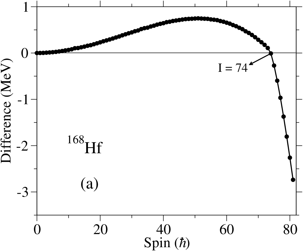

The rotating liquid drop energy at its equilibrium deformation is plotted relative to the fixed reference in Fig. 10(a). This value is thus showing the difference what concerns spin dependence of the ‘previous’ and ’present’ reference energies. Note that both these references are the same for all bands in one nucleus, but that the mass dependence is somewhat different. It is easy to understand the general structure of the curve in Fig. 10(a). At low spin values, the equilibrium deformation of the rotating liquid drop energy is spherical corresponding to a small moment of inertia and thus a larger reference energy. With increasing spin, the increasing oblate deformation of the rotating liquid drop energy corresponds to an increasing rigid body moment of inertia and at , the difference starts to decrease corresponding to the same moment of inertia for the two reference energies. At even higher spin at , the so-called superbackbend occurs [66, 31], when the rotating liquid drop energy loses its stability towards triaxial shape. This corresponds to a rapid increase of the rigid body moment of inertia, leading to large negative values for higher spin values in Fig. 10(a).
It is now easy to understand the differences when the yrast energies are plotted relative to the two differences in Figs. 7 and 10(b), respectively. Thus the general appearance is the same up to but with a larger tendency for decreasing values at low spin with the rotating liquid drop reference. The large differences are however at the highest spin values where the equilibrium deformations in the CNS calculations are generally found at a large deformation with a small moment of inertia which corresponds a large down-slope when this energy is shown relative to the reference, see Fig. 10(b). With the rotating liquid drop reference on the other hand, the reference energies and CNS energies will on the average have the same spin dependence but a not so nice feature is that the large changes in the reference energy at the superbackbend leads to a somewhat strange behaviour of the energies at in Fig. 7.
Let us also point out that the smaller radius parameter combined with the diffuseness correction corresponds to essentially the same rigid moments of inertia in the two reference energies for mass numbers . For smaller mass numbers on the other hand, the diffuseness correction becomes more important. For example, in the region, the spin dependence of the two references is very similar for spin values but they become quite different at higher spin values. Thus, already at , the energy of the rotating liquid drop reference is 2-3 MeV smaller than the standard reference.
V The high-spin bands in 168Hf
V.1 Observed high-spin bands in 168Hf


Experimental excitation energies relative to a rotating liquid drop energy, Erld, as a function of spin and spin, kinematic and dynamic moment of inertia as a function of rotational frequency, , are drawn in Fig. 11(a-d), respectively, for the five bands in 168Hf which are observed well beyond , where pairing correlations should be negligible. From Fig. 11(a) one can see that there is a break in the rotational pattern at and in band 1 and at and in band 3. Furthermore, the spin (Fig. 11(b)) and the moment of inertia (Fig. 11(c)) are triple-valued for band 1 at , i.e. band 1 goes through a full backbend at this spin value. The source of this backbend is the decoupling and spin alignment of an neutron pair from the pairing field [67]. The unsmoothness in and a small peak in (Fig. 11(d)) at in band 3 indicates a weak crossing at this spin. The larger variation of and a huge jump in at () correspond to a larger spin alignment in band 1 and band 3 at this spin. The excitation energy varies smoothly for the ED, TSD1 and TSD2 bands, which means there is no crossing in these bands, even though the ED band displays a small rise or bump in the value with the maximum at MeV.
V.2 Calculated rotational band structures in 168Hf
For the prolate shape minimum (at ) for and , calculated excitation energies for the low-energy configurations in 168Hf are plotted, relative to that of a rotating liquid drop in Figs. 12(a) and (b), respectively.


As pointed out in section IV.2, these configurations are obtained from energy minimization in the deformation space . The yrast line has the configuration or [8,4] in the shorthand notation for spins , see Fig. 12(a). As the angular momentum increases, the lowest state is obtained by exciting a proton from a high- orbital of character to an orbital of character in the shell. Therefore the yrast line is built from the orbitals or [7(10),4] in a short spin range for . Then for , the calculated yrast configuration is [8(11),5] before the [7(11),4] configuration comes lowest in energy at . The single-particle occupancy in these configurations can be understood from Figs. 13(a) and 13(b), where the single-particle Routhians are plotted for protons and neutrons, respectively. The configuration change in the yrast states at is explained from the crossing between the 7/2[523] and 1/2[541] orbitals at MeV. There is a large single-particle shell gap associated with neutron number that continues to MeV, see Fig. 13(b), so the neutron configuration is favoured up to spin values beyond .


The study of the calculated excitation energies for the low-energy configurations with and axially symmetric shapes (Fig. 12(b)) suggests that the yrast line is built on configurations [8(10),4] and [8(11),4] which correspond to and , respectively. These two bands which cross at have the same neutron configuration. The calculated deformations are and for [8(10),4] and [8(11),4] configurations, respectively. In Fig. 12(b), also the [8,5] and [7(10),5] configurations are drawn. They have normal deformation, and cross at spin . The configuration or [8(11),(02)6] in shorthand notation has the deformation . In fact, the two holes in neutron orbitals (see Fig. 13(b)) lead to an enhanced deformation.


The calculated energies at the TSD minimum are drawn in Fig. 14(a) for six low-energy configurations of 168Hf. The associated dynamic moments of inertia are given as a function of rotational frequency in Fig. 14(b). As discussed above, the total energy is minimized in a five dimensional deformation space in this case. All TSD bands are built on the proton configuration or [8(22)]. This is understood from a proton single-particle shell gap at for which is seen in Fig. 15(a).


For neutrons at TSD deformation, a large energy gap is calculated for as anticipated from Fig. 3 and seen Fig. 15(b). This suggests that 169Hf should be a good candidate to observe TSD bands experimentally. The lowest configurations are formed from a neutron hole in the two signatures of the , and orbitals below the gap, resulting in six different neutron configurations. Five of these together with one configuration with two neutrons are


combined with the favored proton configuration, forming six the low-energy triaxial structures shown in Fig. 14(a). Note that all the neutron configurations are built on six neutrons in orbitals, two holes in orbitals and two, three or four holes in orbitals. The calculated deformation is for the [8(22),(42)6(22)] configuration while it is for the other TSD configurations. All of the theoretical TSD bands shown in Fig. 14(a) display a decreasing value of with increasing rotational frequency. At MeV, the value of decreases more strongly for the configuration [8(22),(42)6(22)] and more smoothly for the [8(22),(22)6(11)]. The values of are very close together at MeV and only the configuration [8(22),(22)6(11)] experiences a sharp discontinuity in the moment of inertia at MeV. This discontinuity is because of a crossing in the neutron single particle orbitals between a high- orbital and a low- orbital at MeV. The crossing is indicated by a circle in Fig. 15(b). In the other TSD configurations the orbital has been filled and therefore the strong alignment at MeV is blocked and there is no anomaly in the moment of inertia of them.
In the calculations, no distinction is made between low- and high- orbitals at this large deformation, i.e. only the number of particles of signature and in each -shell is fixed. On the other hand, the configurations are labeled as if such a distinction is made. The labels in Fig. 14(a) refer to the configuration for spin values below . For example, the energy of the configuration labeled [8(22),(22)6(11)] comes down at spin , because of the crossing discussed above. Thus, the band should be labeled [8(22),(22)5(21)] for higher spin values.
V.3 Comparison between calculated and experimental bands in 168Hf
In the upper panels of Fig. 16, experimental excitation energies relative to a rotating liquid drop energy for band 1, band 3, the ED band and the TSD1 and TSD2 bands are drawn as a function of spin. The middle panels of Fig. 16 displays the calculated bands which seem to be closest to these experimental bands. In the lower panels, experimental and theoretical bands are compared (in attention to their parity and signature) and their differences are illustrated.
V.3.1 Band 1
The observed band 1 has a positive parity and signature . Therefore one can find out the structure of this band from the search among the lowest-energy configurations which have (Fig. 12(a)). As it is pointed in section V.2, in Fig. 12(a) the [8,4] and [7(10),4] configurations are the lowest states in energy at spins and , respectively. The [8,4] configuration has an even number of neutrons in orbitals. Thus the observed backbending at in band 1 (see section V.1) could occur in this configuration. Furthermore, the change of structure from [8,4] to [7(10),4] which happens at spin corresponds to the observed break in the rotational pattern at in this band (see Figs. 11(a-d)). Band 1 is compared with the [8,4] and [7(10),4] configurations in the lower panel of Fig. 16(a). As one can see the differences between the theoretical and experimental data for band 1 is rather constant and about MeV at spins if a transition occurs from [8,4] to [7(10),4].
The same structure has been obtained for band 1 in Ref. [16] using the Ultimate Cranker code [68, 29]. However, it is concluded [16] that the occupation of the 1/2 [541] orbital at is related to the crossing between the proton orbitals 9/2[514] and 1/2[541]. This is contrary to our calculations, see Fig. 13(a), where the 9/2[514] orbital is above the Fermi surface and thus the transition is because of the crossing between the 7/2[523] and 1/2[541] orbitals. A closer look at Fig. 5 of Ref. [16] indicates that there are two quasiparticles at similar energies where one should then mainly correspond to a hole in the 7/2[523] orbital and the other to a particle in the 9/2[514] orbital. Then, it appears that if the number of particles should not be changed drastically, the added particle in 1/2[541] should be combined with a hole in 7/2[523], contrary to the conclusion in Ref. [16].
V.3.2 Band 3
Band 3 is observed from to and has . Excitation energies, spin, and behavior of this band are close to those of band 1 (see Figs. 11(a-d)). Thus it seems that this band has a similar deformation as band 1. The lowest-energy states with , see Fig. 12(b), suggest that the [8(10),4] and [8(11),4] configurations should be assigned to band 3. However, as we see in Figs. 11(a-c), in contrast to band 1, band 3 does not backbend at low spins. Therefore the neutron configuration of this band could not be the same as that of band 1 (which has four neutrons in ). As pointed in section V.2, the [8,5] and [7(10),5] configurations have almost the same deformation as band 1 and they also have an odd number of neutrons in orbitals. Thus, even though these two configurations are calculated about 0.5 MeV higher in energy than [8(10),4] and [8(11),4], see Fig. 12(b), they are more suitable candidates for band 3. As one can see in Fig. 12(b), there is a crossing between [8,5] and [7(10),5] at spin which is in agreement with the observed crossing in band 3 experimentally. In the lower panel of Fig. 16(a) band 3 has been compared to the [8,5] and [7(10),5] configurations. With the transition from the [8,5] to the [7(10),5] configuration, the differences between the calculated bands and band 3 is almost constant at -0.5 MeV for spins . Therefore band 3 is built from the neutron configuration and the proton configuration is the same as that for band 1, at and for . This interpretation is similar to that of Ref. [16], but with the same difference as discussed above for band 1.
V.3.3 Band ED
The ED band (called TSD2 in Ref. [14]) has and is observed from to . The calculations, as depicted in Fig. 12(b), show that or the [8(11),4] configuration is lowest in energy for spins This configuration, which corresponds to axially symmetric shape, has been suggested for the ED band in 168Hf [15]. The calculated quadrupole deformation value, , is near normal deformation and far from that of the ED bands in the other Hf isotopes, [10]. The suggested configurations for the ED band in Hf isotopes are all built on the same proton configuration, , but they are coupled to different neutron configurations [10, 15].
A common feature of most interpretations of strongly collective bands is that only the high- intruder orbitals from the higher shells are listed explicitly in the configurations. These high- orbitals are important to build the spin but on the other hand, it is rather the extruder orbitals from the lower shells which build the collectivity. This is evident for the smooth terminating bands [24] and it has been underlined that it is the case for more collective bands, see e.g. [17, 69]. However, to our knowledge, it is only in the present CNS approach that methods have been developed to fix the number of particles in the extruder orbitals. In the present case, the highest orbital is just below the Fermi surface. Thus we consider the configuration with two holes in the upsloping 11/2[505] orbital, i.e. [8(11),(02)6]. This configuration is about 1 MeV higher than [8(11),4] in energy, see Fig. 12(b). However, as pointed in section V.2, the [8(11),(02)6] configuration has a larger value for the quadrupole deformation, , which is in agreement with that of in the other Hf isotopes. Especially, the experimental properties of the ED band are clearly different from those of the valence space band and it is only with the holes in the neutron orbitals that also the theoretical configuration becomes clearly different from the valence space configurations. With the [8(11),(02)6] interpretation for the ED band, the difference between calculations and experiment becomes small and almost constant as seen in the lower panel of Fig. 16(b). It also suggests that such configurations with holes on the neutron orbital, below , should be investigated for the ED bands in other Hf isotopes. Furthermore, as mentioned in Ref. [17], it appears that the same mechanism with holes in the neutron orbitals is responsible for the large quadrupole moment in the SD band of 175Hf.
One problem with the present interpretation is that the [8(11),(02)6] configuration is calculated at an excitation energy which is somewhat too high relative to the configurations assigned to band 3. However, these differences are clearly within the expected uncertainties. For example, if the neutron subshell was placed 0.5 MeV higher in energy, the [8(11),(02)6] configuration would be calculated close to yrast. Note also that when the [8(11),(02)6] configuration is not calculated as yrast, it is straightforward to study it only in approaches like the present one where it is possible to fix the number of holes (or particles) in specific orbitals.
V.3.4 TSD1 and TSD2 Bands
The observed TSD bands in 168Hf [15] have not been linked to the normal-deformed level scheme so their spin and excitation energy can only be estimated. The structure has been suggested as the most probable intrinsic configuration for the TSD1 band. Our calculations with a complete minimization in show that the [8(22),(22)6(11)] configuration is the lowest-energy TSD configuration at spins , see Fig. 14(a). Note that these two suggested configurations are identical with the same high- orbitals occupied but, in the unpaired CNS formalism, also the occupation of other orbitals are specified, including the extruder neutron orbitals with their main amplitudes in the and shells, respectively.
The [8(22),(22)6(11)] configuration with is about 0.5 MeV lower than the next lowest-energy TSD configuration ([8(22),(32)6(21)] with ) at spins . Band TSD1 has been measured up to where the [8(22),(22)6(11)] configuration is calculated only a few hundred keV above the yrast line. Thus, we choose this configuration as our favored candidate for TSD1 and compare the two bands in lower panel of Fig. 16(b). This configuration choice suggests that the observed band TSD1 has negative parity and even spin ().
TSD1 is plotted with an assumed bandhead spin of and with an energy of 11.6 MeV for the bandhead. This leads to a good fit between the observed band and the calculated configuration [8(22),(22)6(11)], where the shorthand notation corresponds to and for the occupation of the open proton and neutron subshells. The calculated quadrupole moment of the configuration [8(22),(22)6(11)] is in the range 11.8-9.9 eb for spin values which is in agreement with the experimentally measured value of eb [14]. However, the calculated quadrupole moment is similar for all configurations in the TSD minimum so it does not help to discriminate between the different configurations listed above.
The configuration assignment to the TSD1 band is certainly preliminary and one might for example argue that we should rather choose a configuration which is calculated yrast at the highest observed spin value, . This would then rather suggest [8(22),(22)6(21)] or [8(22),(32)6(21)] as the favoured choice, i.e. configurations with one more neutron excited to the orbitals. In addition to the high- particles, the TSD minimum is characterized by at least 2 and 2 neutron holes. This is the case also for the calculations presented in Ref. [15] even though these holes are not specified in the configuration labels used in that reference. As pointed out in section III, these holes are important to create the smooth collective bands where it is mainly the holes which induces the triaxial shape.
Based on comparisons with calculations and with the TSD1 band, see Figs. 14(a) and 16(b), the spin and bandhead energy for the TSD2 band are estimated to be and 14.7 MeV, respectively. As pointed out above, the next lowest TSD configuration for is [8(22),(32)6(21)] with . This configuration is yrast for . Therefore it seems that this configuration is a reasonable candidate for the observed TSD2 band. As one can see in the lower panel of Fig. 16(b), the energy difference between the TSD2 band and the [8(22),(32)6(21)] configuration is small and rather constant for . Considering the configurations in Fig. 14(a), another possible choice is the [8(22),(22)6(21)] configuration with . Thus, the present calculations suggest that compared with TSD1, TSD2 has the same proton configuration but with one neutron excited to from either the orbitals or from the orbitals. This leads to odd spin values () but undetermined parity for TSD2.

The configurations of the TSD1 and TSD2 bands could be interpreted by considering the behavior of the dynamic moment of inertia. Although the spin assignments for these TSD bands may need revising, the dynamic moments of inertia are not affected by these changes. A smooth decrease in the moment is observed for the TSD1 and TSD2 bands, see Fig. 17, which is consistent with the general trend of TSD bands in the other Hf isotopes [11, 13, 70]. Fig. 17 also displays three configurations that have characteristics similar to the two observed TSD bands. On the other hand, the absolute value of is somewhat smaller in calculations than in experiment, which can also be concluded from the positive curvature in the difference curves in the lower panel of Fig. 16(b). The TSD1 band and the [8(22),(22)6(11)] configuration have rather similar slopes in throughout the observed frequency range. The value of for the TSD2 band has a behavior similar to that of two suggested configurations but the calculated dynamic moment of inertia is the same for the others TSD configurations, see Fig. 14(b), so it does not help to choose a favorable configuration for the TSD2 band.
VI Additional comments on the TSD bands in nuclei.
VI.1 Full minimization in Lu isotopes and 158Er
We have examined the full minimization approach in the hexadecapole deformation space (see sect. IV.2) for TSD configurations in Lu isotopes. Our calculations show that this effect will typically decrease the minimum energy by 200 keV in the observed spin region (). The maximum gain of about 300 keV is obtained in 165Lu, which has a large hexadecapole equilibrium deformation, . These effects will lead to some minor corrections on the results presented in sect. III but they will clearly not change the general conclusions.
Similar calculations have been carried out for 158Er where, according to studies in Ref. [20, 21], three well-defined TSD minima with deformations and are seen. Our calculations show that a complete minimization in has only a small influence on the energy. The gain in energy is always smaller than 200 keV for the TSD configurations in 158Er.
VI.2 Effective alignments in a larger mass range from 158Er to 168Hf


It is instructive to consider the alignment in a larger mass range outside the Lu isotopes. Therefore, in Fig. 18 the difference in alignment between the lowest TSD bands in 163Lu and 168Hf is shown for the experimental bands and for the configurations we have assigned to these bands. In the calculations, we have chosen the spin values for the unlinked band in 168Hf based on the present calculations and this will naturally lead to a general agreement between 163Lu and 168Hf what concerns the effective alignment. Considering the orbitals which are filled in 168Hf but not in 163Lu, it is mainly the proton and the and neutrons which build the large effective alignment of almost while the filling of two neutron orbitals will only have a small contribution to .
It is then also instructive to compare the spin difference between the lowest TSD bands in 158Er and 163Lu which is drawn for experiment and calculations in the upper and lower panels of Fig. 18, respectively. Several possible theoretical assignments are shown, corresponding to the lowest-energy configurations in the minima with (TSD1), (TSD2) and (TSD3), where the different minima are labelled as in Ref. [21]. Furthermore, it should be noted that the spin values in 158Er are not known and have been chosen in the range as suggested in Ref. [17]. If these spin values are increased (decreased) by , it will correspond to a constant decrease (increase) for values of the curve in the upper panel by , but with no change of the spin dependence.
The TSD1 configuration of 158Er and the TSD band of 163Lu have similar deformations so the corresponding value of measures the spin contribution from the orbitals which are filled in 163Lu but not in 158Er, i.e. 2 and one protons and 2 neutrons. They will then give a negative contribution to in agreement with general expectations for orbitals in the middle of a -shell, see e.g. Fig. 27 of Ref. [23]. When it comes to the configurations in the TSD2 and TSD3 minima, the value of does not correspond to the contribution of any specific orbitals because these configurations do not have a common core with 163Lu.
In any case, it is still possible to define the difference in spin value for a fixed frequency and the comparison between experiment and calculations in Fig. 18 shows that it is necessary to increase the spin values in 158Er by to get agreement at the highest frequencies for the TSD3 configurations. For the TSD2 configuration on the other hand, experiment and calculations come close for all frequencies with present spin values. Note especially that a down-slope is seen both in experiment and calculations for frequencies MeV. This down-slope corresponds to an additional alignment of in this frequency range for 158Er relative to 163Lu. Such an alignment gives rise to a bump in the moment of inertia as discussed in some detail for the corresponding bands in 159,160Er in Ref. [20]. As discussed there, the alignment is caused by a crossing between an proton orbital and the lowest orbital. As seen in Fig. 18, while the observed alignment is approximately reproduced for the TSD2 configuration, no similar alignment is seen in the TSD1 and TSD3 configurations. In Ref. [20], a bump in the moment of inertia for the TSD1 band, caused by a crossing between the neutron orbitals, was discussed. This is however a considerably broader bump corresponding to an alignment in a larger frequency range which is not seen as any well-defined alignment in Fig. 18. For the TSD3 configuration, no specific alignment is seen in Fig. 18 and no crossing between orbitals is observed in Fig. 15 which could give raise to such an alignment.
The conclusion from the present analysis of the alignments would thus be that the TSD2 configuration, i.e. the configuration, which is the preferred assignment for the yrast TSD band in 158Er. This is also the preferred configuration when comparing the transitional quadrupole moment [21], even though the value of for the TSD3 configuration is not much different. However, if a TSD3 configuration is assigned, it appears to correspond to an unrealistic increase of the spin values in the band compared with the values which appears most realistic from an experimental point of view [17]. The assignment of a negative configuration is in disagreement with Ref. [22] where it is concluded that a TSD2 minimum would be instable towards the TSD1 minimum in the tilted axis degree of freedom. This conclusion however requires that the TSD1 minimum is (considerably) lower in energy than the TSD2 minimum which is the outcome of the CNS calculations as well as the calculations of Ref. [22]. However, the relative energies of the three TSD minima are clearly uncertain within at least MeV. Thus, considering only the calculated energies, it could be a configuration in any of the three TSD minima which should be assigned to observed yrast TSD band in 158Er. One may also note that with present interpretations, there is no strong relation between the TSD bands in 158Er and 168Hf.
VII Conclusions
In this study, we have made some modifications when solving the Hamiltonian in configuration-dependent cranked Nilsson-Strutinsky formalism in order to test the accuracy of some approximations. The nucleus 168Hf is used as a test case and the observed highest-spin bands in this nucleus are analyzed.
An important feature of the CNS formalism is that the off-shell matrix elements in the rotating harmonic oscillator basis are neglected in order to make it possible to fix configurations in more detail. For the yrast states, it is however straightforward to include all couplings and compare with the approximate CNS results. We conclude that the neglect of the off-shell elements of the Hamiltonian matrix is acceptable; i.e. for the deformations and rotational frequencies which are reached in 168Hf, it only leads to small errors which are essentially negligible compared with other uncertainties. This is also true for the cut-off error due to the limited number of oscillator shells in the basis, where our calculations show that if more than 9 shells () are included, both the total discrete energy and the total smoothed energy decrease, which means that the shell energy and thus also the total rotational energy is almost unchanged.
The total energy was minimized in the full hexadecapole space indicating that for axially symmetric shape, it is generally sufficient to include only the standard degree of freedom which does not break the axial symmetry. On the other hand, at large triaxial deformation, it appears necessary to minimize the energy in all three hexadecapole deformation parameters, . The study of the deformation space shows that in 168Hf, the energy of the axially symmetric bands with normal deformation could as well be minimized in the restricted deformation space , while the energy of the TSD bands should be minimized in the deformation space . We used these results and studied the structure of the experimental bands band 1, band 3, band ED and bands TSD1 and TSD2 in 168Hf.
In our studies of the high-spin bands of 168Hf, the general conclusions are the same as in Refs. [15, 16] but still with some important differences. Thus, we conclude that the crossing observed around in the normal deformed bands are created when a particle is excited to the down-sloping 1/2[541] orbital but rather from the 7/2[523] orbital and not from the 9/2[514] orbital suggested in Ref. [16]. The different conclusions are understood from the fact that the number of particles is preserved in the unpaired formalism, while quasi-particle excitations with a fixed Fermi energy [16] could lead to significant changes in the number of particles. More important is however our suggestion that the ED band is built with two holes in the extruder orbitals. With such an excitation, the configuration is clearly different from that of the normal deformed bands with a calculated transitional quadrupole moment in closer agreement with experiment. Because this configuration is not calculated as yrast, it is straightforward to analyze it only in formalisms where excited configurations with the same quantum numbers can be distinguished, e.g. by the number of particles (or holes) in high- orbitals. For the TSD1 and TSD2 bands, we conclude that they are formed in a strongly deformed triaxial minimum with several particles excited to high- intruder orbitals. This agrees with the assignment in Ref. [15] what concerns TSD1. However, while only the high- particles were considered in that reference, the holes in the extruder orbitals are as important according to our analyses, where it is mainly the neutron orbitals which induces the triaxial shape.
As a background for the study of the Hf bands, we did also investigate the filling of the orbitals of the TSD bands in Lu isotopes. These bands are naturally understood as having a proton configuration with one orbital occupied, compared with two such orbitals filled in the larger deformation TSD bands of 168Hf. The neutron configurations in the range are characterized by a successive filling of down-sloping orbitals in a region of low level-density which is created below four extruder orbitals emerging from the and shells, see Figs. 1 and 3.
The relative alignments, [37], between the TSD bands in the different nuclei was analyzed where the general features are understood from the contribution of the different orbitals which become occupied. Especially, it was concluded that the specific features of the yrast ultrahigh-spin band in 158Er are best understood if this band is built in the TSD minimum with , i.e. for rotation around the intermediate axis.
This work was supported in part by the Swedish Research Council and the Iranian Ministry of Science, Research and Technology.
References
- [1] I. Ragnarsson, Phys. Rev. Lett. 62, 2084 (1989).
- [2] S. Åberg, Nucl. Phys. A520, 35c (1990).
- [3] W. Nazarewicz and I. Ragnarsson, Proc. ’Future Directions in Nuclear Physics with 4 gamma detection Systems of the New generation’, Strasbourg, March 1991, eds. J. Dudek and B. Haas (AIP Conf. Proc. 259, 1992) p. 193.
- [4] H. Schnack-Petersen et al., Nucl. Phys. A 594, 174 (1995).
- [5] R. Bengtsson and H. Ryde, Eur. Phys. J. A 22, 355 (2004).
- [6] S. Ødegård et al., Phys. Rev. Lett. 86, 5866 (2001).
- [7] G. Schönwasser et al., Phys. Lett. B 552, 9 (2003).
- [8] H. Amro et al., Phys. Lett. B 553, 197 (2003).
- [9] A. Neusser-Neffgen et al., Phys. Rev. C 73, 034309 (2006).
- [10] Y. C. Zhang et al., Phys. Rev. C 76, 064321 (2007).
- [11] M. K. Djongolov et al., Phys. Lett. B 560, 24 (2003).
- [12] D. J. Hartley et al., Phys. Lett. B 608, 31 (2005).
- [13] D. T. Scholes et al., Phys. Rev. C 70, 054314 (2004).
- [14] H. Amro et al., Phys. Lett. B 506, 39 (2001).
- [15] R. B. Yadav et al., Phys. Rev. C 78, 044316 (2008).
- [16] R. B. Yadav et al., Phys. Rev. C 80, 064306 (2009).
- [17] E. S. Paul et al., Phys. Rev. Lett. 98, 012501 (2007).
- [18] A. Aguilar et al., Phys. Rev. C 77, 021302(R) (2008).
- [19] C. Teal et al., Phys. Rev. C 78, 017305 (2008).
- [20] J. Ollier et al., Phys. Rev. C 80, 064322 (2009).
- [21] X. Wang et al., Phys. Lett. B 702, 127 (2011).
- [22] Yue Shi, J. Dobaczewski, S. Frauendorf, W. Nazarewicz, J.C. Pei, F.R. Xu and N. Nikolov, Phys. Rev. C 108, 092501 (2012).
- [23] T. Bengtsson and I. Ragnarsson, Nucl. Phys. A 436, 14 (1985).
- [24] A.V. Afanasjev et al., Phys. Rep. 322, 1 (1999).
- [25] B.G. Carlsson and I. Ragnarsson, Phys. Rev. C 74, 011302(R) (2006).
- [26] I. Ragnarsson, Slide Report, Conference ‘Nuclear Structure 2008 (NS2008)’, Michigan State University, June 3-6, 2008.
- [27] S.G. Nilsson, Mat. Fys. Medd. Dan. Vid. Selsk, 29, No. 16 (1955).
- [28] S.G. Nilsson and I. Ragnarsson, Shapes and shells in Nuclear Structure (Cambridge University Press, Cambridge, England, 1995).
- [29] T. Bengtsson, Nucl. Phys. A 512, 124 (1990); A 496, 56 (1989).
- [30] V.M. Strutinsky, Nucl. Phys. A 122, 1 (1968).
- [31] G. Andersson et al., Nucl. Phys. A 268, 205 (1976).
- [32] K. Pomorski and J. Dudek, Phys. Rev. C 67, 044316 (2003).
- [33] S.G. Rohozinski, Report of the Institute for Nuclear Research, Warsaw, INR 1520/VII/PH/B; S.G. Rohozinski and A. Sobiczewski, Acta. Phys. Pol. B 2, 1001 (1981).
- [34] J. Dudek, K. Mazurek, B. Nerlo-Pomorska, Acta. Phys. Pol. B 35, 1263 (2004).
- [35] A. Staszczak, J. Dobaczewski, W. Nazarewicz, Int. J. Mod. Phys. E 14, 395 (2005).
- [36] A. Sobiczawski, M. Kowal. L. Shvedov, Acta. Phys. Pol. B 38, 1577 (2007).
- [37] I. Ragnarsson, Nucl. Phys. A 557, 167c (1993).
- [38] A. Bohr and B. R. Mottelson, Nuclear Structure (Benjamin, New York, 1975), Vol. 2.
- [39] W. Koepf and P. Ring, Nucl. Phys. A 493, 61 (1989).
- [40] J. König and P. Ring, Phys. Rev. Lett. 71, 3079 (1993).
- [41] A. V. Afanasjev, J. König, and P. Ring, Nucl. Phys. A 608, 107 (1996).
- [42] A. V. Afanasjev, J. König, and P. Ring, Phys. Rev. C 60, 051303(R) (1999).
- [43] A. V. Afanasjev, P. Ring, and J. König, Nucl. Phys. A 676, 196 (2000).
- [44] D. Vretenar, A. V. Afanasjev, G. Lalazissis and P. Ring, Phys. Rep. 409, 101 (2005).
- [45] A. V. Afanasjev and S. Frauendorf, Phys. Rev. C 71, 064318 (2005).
- [46] B.G. Carlsson, et al., Phys. Rev. C 78, 034316 (2008).
- [47] R. Wadsworth et al., Phys. Lett. B 701, 306 (2011).
- [48] I. Ragnarsson, B. G. Carlsson and H. Ryde, Inter. Jour. Mod. Phys. E, 19, 590 (2010).
- [49] Hailiang Ma, et al., to be publ.
- [50] B. Haas et al., Nucl. Phys. A 561, 251 (1993).
- [51] A.V. Afanasjev, G.A. Lalazissis and P. Ring, Nucl. Phys. A 634, 395 (1998).
- [52] S. E. Larsson, P. Möller, and S. G. Nilsson, Phys. Scr. A 10, 53 (1974).
- [53] P. Bringel et al., Eur. Phys. J. A 16, 155 (2003).
- [54] P. Bringel et al., Phys. Rev. C 73, 054314 (2006).
- [55] D. R. Jensen et al., Nucl. Phys. A 703, 3 (2002).
- [56] P. Bringel et al., Phys. Rev. C 75, 044306 (2007).
- [57] S. Törmänen et al., Phys. Lett. B 454, 8 (1999).
- [58] H. Amro et al., Phys. Rev. C 71, 011302 (2005).
- [59] I. Ragnarsson, Nucl. Phys. A 520, 67c (1990).
- [60] H. Schnare et al., Phys. Rev. C 54, 1598 (1996).
- [61] J. Silverberg, Master Theses, Physics Dept., Lund University, 2010, unpubl.
- [62] S. Cohen, F. Plasil and W.J. Swiatecki, Ann. of Phys. (N.Y.) 82, 557 (1974).
- [63] W.D. Myers and W.J. Swiatecki, Nucl. Phys. A 81, 1 (1966).
- [64] P. Möller, J.R. Nix, W.D. Myers and W.J. Swiatecki, At. Data Nucl. Data Tables, 59, 185 (1995).
- [65] K.T.R. Davies and J.R. Nix, Phys. Rev. C 14, 495 (1976).
- [66] M.V. Banaschik, R.S. Simon, P. Colombani, D.P. Soroka, F.S. Stephens and R.M. Diamond, Phys. Rev. Lett. 14, 892 (1975).
- [67] R.V.F. Janssens, M.J.A. de Voigt, H. Sakai, H.J.M. Aarts, C.J. van der Poel, H.F.R. Arciszewski, D.E.C. Scherpenzeel and J. Vervier, Phys. Lett. B 106, 475 (1981).
- [68] R. Bengtsson, www.matfys.lth.se/ ragnar/ultimate.html.
- [69] I. Ragnarsson, Acta Phys. Pol. B 27, 33 (1996).
- [70] A. Neusser et al., Eur. Phys. J. A 15, 439 (2002).