A Simple Optimal Binary Representation of Mosaic Floorplans and Baxter Permutations
Abstract
A floorplan is a rectangle subdivided into smaller rectangular sections by horizontal and vertical line segments. Each section in the floorplan is called a block. Two floorplans are considered equivalent if and only if there is a one-to-one correspondence between the blocks in the two floorplans such that the relative position relationship of the blocks in one floorplan is the same as the relative position relationship of the corresponding blocks in another floorplan. The objects of Mosaic floorplans are the same as floorplans, but an alternative definition of equivalence is used. Two mosaic floorplans are considered equivalent if and only if they can be converted to each other by sliding the line segments that divide the blocks.
Mosaic floorplans are widely used in VLSI circuit design. An important problem in this area is to find short binary string representations of the set of -block mosaic floorplans. The best known representation is the Quarter-State Sequence which uses bits. This paper introduces a simple binary representation of -block mosaic floorplan using bits. It has been shown that any binary representation of -block mosaic floorplans must use at least bits. Therefore, the representation presented in this paper is optimal (up to an additive lower order term).
Baxter permutations are a set of permutations defined by prohibited subsequences. Baxter permutations have been shown to have one-to-one correspondences to many interesting objects in the so-called Baxter combinatorial family. In particular, there exists a simple one-to-one correspondence between mosaic floorplans and Baxter permutations. As a result, the methods introduced in this paper also lead to an optimal binary representation of Baxter permutations and all objects in the Baxter combinatorial family.
1 Introduction
In this section, we introduce the definition of mosaic floorplans and Baxter permutations, describe their applications and previous work in this area, and state our main result.
1.1 Floorplans and Mosaic Floorplans
Definition 1
A floorplan is a rectangle subdivided into smaller rectangular subsections by horizontal and vertical line segments such that no four subsections meet at the same point.


The smaller rectangular subsections are called blocks. Figure 1 shows three floorplans, each containing 9 blocks. Note that the horizontal and vertical line segments do not cross each other. They can only form T-junctions (, , , and ).
The definition of equivalent floorplans does not consider the size of the blocks of the floorplan. Instead, two floorplans are considered equivalent if and only if their corresponding blocks have the same relative position relationships. The formal definition is given below.
Definition 2
Let be a floorplan with as its set of blocks. Let be another floorplan with as its set of blocks. and are considered equivalent floorplans if and only if there is a one-to-one mapping such that the following conditions hold:
- 1.
For any two blocks , and share a horizontal line segment as their common boundary with above if and only if and share a horizontal line segment as their common boundary with above .
- 2.
For any two blocks , and share a vertical line segment as their common boundary with to the left of if and only if and share a vertical line segment as their common boundary with to the left of .
In Figure 1, (a) and (b) have the same number of blocks and the position relationships between their blocks are identical. Therefore, (a) and (b) are equivalent floorplans. However, (c) is not equivalent to either.
The objects of mosaic floorplans are the same as the objects of the floorplans. However, mosaic floorplans use a different definition of equivalence. Informally speaking, two mosaic floorplans are considered equivalent if and only if they can be converted to each other by sliding the horizontal and vertical line segments. The equivalence of the mosaic floorplans is formally defined by using the horizontal constraint graph and the vertical constraint graph [9]. The horizontal constraint graph describes the horizontal relationship between the vertical line segments of a floorplan. The vertical constraint graph describes the vertical relationship between the horizontal line segments of a floorplan. The formal definitions are given below.
Definition 3
Let be a floorplan.
- 1.
The horizontal constraint graph of is a directed graph. The vertex set of 1-to-1 corresponds to the set of the vertical line segments of . For two vertices and in , there is a directed edge if and only if there is a block in such that the vertical line segment corresponding to is on the left boundary of and the vertical line segment corresponding to is on the right boundary of .
- 2.
The vertical constraint graph of is a directed graph. The vertex set of 1-to-1 corresponds to the set of the horizontal line segments of . For two vertices and in , there is a directed edge if and only if there is a block in such that the horizontal line segment corresponding to is on bottom boundary of and the horizontal line segment corresponding to is on the top boundary of .
The graphs in Figure 2 are the constraint graphs of all three floorplans shown in Figure 1 (a), (b), and (c). Note that the bottom (top, left, right, respectively) boundary of the floorplan is represented by the south (north, west, east, respectively) vertex labeled by S (N, W, E, respectively) in the constraint graphs. Also note that each edge in (, respectively) corresponds to a block in the floorplan.


Definition 4
Two mosaic floorplans are equivalent mosaic floorplans if and only if they have identical horizontal constraint graphs and vertical constraint graphs.
Thus all three floorplans shown in Figure 1 (a), (b), and (c) are equivalent mosaic floorplans. Note that the floorplan in Figure 1 (c) is obtained from the floorplan in Figure 1 (b) by sliding the horizontal line segment between the blocks and downward; the horizontal line segment between the blocks and upward; the vertical line segment between the blocks and to the right.
1.2 Applications of Floorplans and Mosaic Floorplans
Floorplans and mosaic floorplans are used in the first major stage (called floorplanning) in the physical design cycle of VLSI (Very Large Scale Integration) circuits [10]. The blocks in a floorplan correspond to the components of a VLSI chip. The floorplanning stage is used to plan the relative position of the circuit components. At this stage, the blocks do not have specific sizes assigned to them yet. So only the position relationship between the blocks are considered.
For a floorplan, the wires between two blocks run cross their common boundary. In this setting, two equivalent floorplans provide the same connectivity between blocks. For a mosaic floorplan, the line segments are the wires. Any block with a line segment on its boundary can be connected to the wires represented by the line segment. In this setting, two equivalent mosaic floorplans provide the same connectivity between blocks.
One of the main problems in this area is to find a short binary representation of floorplans and mosaic floorplans. These representations are used by various algorithms to generate floorplans in order to solve various VLSI layout optimization problems. Shorter representation allows more efficient optimization algorithms.
1.3 Baxter Permutations
Baxter permutations are a set of permutations defined by prohibited subsequences. They were first introduced in [3]. It was shown in [8] that the set of Baxter permutations has one-to-one correspondences to many interesting objects in the so-called Baxter combinatorial family. For examples, [4] showed that plane bipolar orientations with edges have a one-to-one correspondence with Baxter permutations of length . [5] establishes a relationship between Baxter permutations and pairs of alternating sign matrices.
In particular, it was shown in [1, 6, 18] that mosaic floorplans are one of the objects in the Baxter combinatorial family. A simple and efficient one-to-one correspondence between mosaic floorplans and Baxter permutations was established in [1, 6]. As a result, any binary representation of mosaic floorplans can also be converted to a binary representation of Baxter permutations.
1.4 Previous Work on Representations of Floorplans and Mosaic Floorplans
Because of their applications in VLSI physical design, the representations of floorplans and mosaic floorplans have been studied extensively by mathematicians, computer scientists and electrical engineers. Although their definitions are similar, the combinatorial properties of floorplans and mosaic floorplans are quite different. The following is a partial list of previous research on floorplans and mosaic floorplans.
Floorplans:
There is no known formula for calculating , the number of -block floorplans. The first few values of (starting from ) are . Researchers have been trying to bound the range of . In [2], it was shown that there exists a constant and . This means that for large . The upper bound of is reduced to in [7].
Algorithms for generating floorplans were presented in [12]. In [16], a -bit binary string representation of -block floorplans was found. A different -bit binary string representation of -block floorplans was presented in [17]. The shortest known binary string representation of -block floorplans was given in [15]. This representation uses bits.
Since for large [2], any binary string representation of -block floorplans must use at least bits. Closing the gap between the known -bit binary representation and the lower bound remains an open research problem [15].
Mosaic Floorplans:
It was shown in [6] that the set of -block mosaic floorplans has a one-to-one correspondence to the set of Baxter permutations, and the number of -block mosaic floorplans equals to the Baxter number , which is defined as the following:
In [14], it was shown that . The first few Baxter numbers (staring from ) are .
There is a long list of papers on representation problem of mosaic floorplans. [11] proposed a sequence pair (SP) representation. Two sets of permutations are used to represent the position relations between blocks. The length of the representation is bits.
[9] proposed a corner block list (CB) representation for mosaic floorplans. The representation consists of a list of blocks, a binary string of bits, and a binary string of bits. The total length of the representation is bits.
[19] proposed a twin binary sequences (TBS) representation for mosaic floorplans. The representation consists of 4 binary strings , where is a permutation of integers , and the other three strings are or bits long. The total length of the representation is .
A common feature of above representations is that each block in the mosaic floorplan is given an explicit name (such as an integer between 1 and ). They all use at least one list (or permutation) of these names in the representation. Because at least bits are needed to represent every integer in the range , the length of these representations is inevitably at least bits.
A different approach was introduced in [18]. They use a pair of twin pair binary trees and to represent mosaic floorplans. The blocks of the mosaic floorplan are not given explicit names. Rather, the shape of the two trees and are used to encode the position relations of blocks. In this representation, each tree consists of nodes. Thus, each tree can be encoded by using bits. So the total length of the representation is bits. They also proposed an alternate representation using a pair of -node trees. However, the nodes in the two trees are given names, and the length of the representation is at least .
In [13], a representation called quarter-state-sequence (QSS) was presented. It uses a sequence that represents the configuration of one of the corners of the mosaic floorplan. The length of the sequence representation is bits. This is the best known representation for mosaic floorplans.
Because the number of -block mosaic floorplans equals the Baxter number, at least bits are needed to represent mosaic floorplans.
1.5 Our Main Result
Theorem 1
The set of -block mosaic floorplans can be represented by bits, which is optimal up to an additive lower order term.
Most binary representations of mosaic floorplans discussed in section 1.4 are fairly complex. In contrast, the representation introduced in this paper is very simple and easy to implement.
By using the simple one-to-one correspondence between mosaic floorplans and Baxter permutations described in [1], the methods presented in this paper also work on Baxter permutations. Hence, our optimal representation of mosaic floorplans also leads to an optimal representation of Baxter permutations and all other objects in the Baxter combinatorial family.
2 Optimal Binary Representation of Mosaic Floorplans
In this section, we describe our optimal representation of mosaic floorplans.
2.1 Standard Form of Mosaic Floorplans
In the following, we introduce the notion of standard form of mosaic floorplans, which plays a central role in our representation.
Let be a mosaic floorplan. Let be a horizontal line segment in . The upper segment set of and the lower segment set of are defined as the following:
ABOVE the set of vertical line segments of that intersect and are above .
BELOW the set of vertical line segments of that intersect and are below .
Similarly, for a vertical line segment in , the left segment set of and the right segment set of are defined as the following:
LEFT the set of horizontal segments of that intersect and are on the left of .
RIGHT the set of horizontal segments of that intersect and are on the right of .


Definition 5
A mosaic floorplan is in standard form if the following hold:
The mosaic floorplan shown in Figure 1 (c) is the standard form of mosaic floorplans shown in Figure 1 (a) and Figure 1 (b).
The standard form of a mosaic floorplan can be obtained by sliding its vertical and horizontal line segments. Because of the equivalence definition of mosaic floorplans, and are considered the same mosaic floorplans. For a given , can be obtained in linear time by using the horizontal constraint graphs and vertical constraint graphs described in [9]. From now on, all mosaic floorplans are assumed to be in standard form.
2.2 Staircases
Definition 6
A staircase is an object that satisfies the following conditions:
- 1.
The border contains a line segment on the -axis and a line segment on the -axis.
- 2.
The remainder of the border is a non-increasing line segments consisting of vertical and horizontal line segments.
- 3.
The interior is divided into smaller rectangular subsections by horizontal and vertical line segments.
- 4.
No four subsections meet at the same point.

A step of a staircase is a horizontal line segment on the border of , excluding the -axis. Figure 4 shows a staircase with blocks and steps. Note that a mosaic floorplan is just a special case of a staircase with step.
2.3 Deletable Rectangles
Definition 7
A deletable rectangle of a staircase is a block that satisfies the following conditions:
- 1.
Its top edge is completely contained in the border of .
- 2.
Its right edge is completely contained in the border of .
In the staircase shown in Figure 4, the block is the only deletable rectangle. The concept of deletable rectangles is a key idea for the methods introduced in this paper. This concept was originally defined in [15] for their -bit representation of floorplans. However, a modified definition of deletable rectangles is used in this paper to create a -bit representation of mosaic floorplans.
Lemma 1
The removal of a deletable rectangle from a staircase results in another staircase unless the original staircase contains only one block.
Proof: Let be a staircase with more than one block and let be a deletable rectangle in . Define to be the object that results when is removed from . Because the removal of still leaves with at least one block, the border of still contains a line segment on the -axis and a line segment on the -axis, so condition (1) of a staircase holds for . Removing will not cause the remainder of the border to have an increasing line segment because the right edge of must be completely contained in the border, so condition (2) of a staircase also holds for . The removal of does not form new line segments, so the interior of will still be divided into smaller rectangular subsections by vertical and horizontal line segments, and no four subsections in will meet at the same point. Thus, conditions (3) and (4) of a staircase hold for . Therefore, is a staircase.
We can now outline the basic ideas of our representation. Given a mosaic floorplan , we remove deletable rectangles of one by one. By Lemma 1, this results in a sequence of staircases, until only one block remains. We record necessary location information of these deletable rectangles (which will be the binary representation of ) so that we can reconstruct the original floorplan . However, if there are multiple deletable rectangles for these staircases, we will have to use more bits than we can afford. Fortunately, the following key lemma shows that this does not happen.
Lemma 2
Let be a -block mosaic floorplan in standard form. Let , and let () be the staircase obtained by removing a deletable rectangle from .
- 1.
There is a single, unique deletable rectangle in for .
- 2.
is adjacent to for .
Proof: The proof is by reverse induction.
Clearly, has only one deletable rectangle located at the top right corner of .
Assume that () has exactly one deletable rectangle . Let be the horizontal line segment in that contains the bottom edge of , and let be the vertical line segment in that contains the left edge of (see Figure 5). Let be the uppermost block in whose right edge aligns with , and let be the rightmost block in whose top edge aligns with . After is removed from , and are the only candidates for deletable rectangles of the resulting staircase . There are two cases:


- 1.
The line segments and form a -junction (see Figure 5 (a).) Then, the bottom edge of must be below because is a standard mosaic floorplan, and is not a deletable rectangle in . Thus, the block is the only deletable rectangle in .
- 2.
The line segments and form a -junction (see Figure 5 (b).) Then, the left edge of must be to the left of because is a standard mosaic floorplan, and is not a deletable rectangle in . Thus, the block is the only deletable rectangle in .
In both cases, only one deletable rectangle (which is either or ) is revealed when the deletable rectangle is removed. Because there is only one deletable rectangle in , all subsequent staircases contain exactly one deletable rectangle. Thus, (1) is true. Also, is adjacent to in both cases, so (2) is true.
Let be a staircase and be a deletable rectangle of whose top side is on the -th step of . There are four types of deletable rectangles.


- 1.
Type :
- (a)
The top side of is the entire -th step.
- (b)
The right side of intersects the -th step.
- (c)
The deletion of decreases the number of steps by one.
- (a)
- 2.
Type :
- (a)
The top side of is only a part of the -th step.
- (b)
The right side of intersects the -th step.
- (c)
The deletion of does not change the number of steps.
- (a)
- 3.
Type :
- (a)
The top side of is the entire -th step.
- (b)
The right side of is only a part of the right side of the -th step (namely the right-bottom corner of is a shape junction).
- (c)
The deletion of does not change the number of steps.
- (a)
- 4.
Type :
- (a)
The top side of is only a part of the -th step.
- (b)
The right side of is only a part of the right side of the -th step (namely the right-bottom corner of is a shape junction).
- (c)
The deletion of increases the number of steps by one.
- (a)
2.4 Optimal Binary Representation
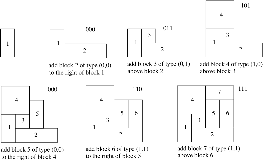
Our binary representation of mosaic floorplans depends on the fact that a mosaic floorplan is a special case of a staircase and the fact that the removal of a deletable rectangle from a staircase results in another staircase. The binary string used to represent records the unique sequence of deletable rectangles that are removed in this process. The information stored by this binary string enable us to reconstruct the original mosaic floorplan .
A 3-bit binary string is used to record the information for each deletable rectangle . The string has two parts: The type and the location of . To record the type of , the bits corresponding to its type is stored directly. To store the location, we note that, by Lemma 2, two consecutive deletable rectangles and are adjacent to each other. Thus, they must share either a horizontal edge or a vertical edge. A single bit can be used to record the location of with respect to : a 1 if they share a horizontal edge, and a 0 if they share a vertical edge.
Encoding Procedure:
Let be the -block mosaic floorplan to be encoded. Starting from , remove the unique deletable rectangles , where , one by one. For each deletable rectangle , two bits are used to record the type of , and one bit is used to record the type of the common boundary shared by and .
Decoding Procedure:
The decoding procedure simply reverses the process of removing deletable rectangles. The process starts with the staircase , which is a single rectangle. Each staircase can be reconstructed from the staircase by using the three-bit code for the deletable rectangle . The three-bit code records the type of and the type of edge shared by and , so can be uniquely added to . Thus, the decoding procedure can reconstruct original mosaic floorplan .
Figure 7 show an example of the reconstruction of a mosaic floorplan from its representation:
000 011 101 000 110 111
The lower left block of the mosaic floorplan (which is the only block of ) does not need any information to be recorded. Each of the other blocks of needs three bits. Thus the total length of the binary representation of is bits. This completes the proof of Theorem 1.
3 Conclusion
In this paper, we introduced a binary representation of -block Mosaic floorplans. The representation uses bits. Since any representation of -block mosaic floorplans requires at least bits [14], our representation is optimal (up to an additive lower term). Our representation is very simple and easy to implement.
Mosaic floorplans are known to have a simple one-to-one correspondence with Baxter permutations. So the method used to represent mosaic floorplans in this paper also lead to an optimal bits representation of Baxter permutation of length , and all objects in the Baxter combinatorial family.
References
- [1] Eyal Ackerman, Gill Barequet, and Ron Y. Pinter. A bijection between permutations and floorplans, and its applications. Discrete Applied Mathematics, 154:1674–1684, 2006.
- [2] Kazuyuki Amano, Shin’ichi Nakano, and Katsuhisa Yamanaka. On the number of rectangular drawings: Exact counting and lower and upper bounds. IPSJ SIG Notes 2007-AL-115-5C, pages 33–40, 2007.
- [3] G. Baxter. On fixed points of the composite of commuting functions. In Proceedings American Mathematics Society 15, pages 851–855, 1964.
- [4] Nicloas Bonichon, Mirelle Bousquet-Mélou, and Éric Fusy. Baxter permutations and plane bipolar orientations. Séminaire Lotharingien de Combinatoire, 61A, 2010.
- [5] Hal Canary. Aztec diamonds and baxter permutations. The Electronic Journal of Combinatorics, 17, 2010.
- [6] S. Dulucq and O. Guibert. Baxter permutations. Discrete Mathematics, 180:143–156, 1998.
- [7] Ryo Fujimaki, Youhei Inoue, and Toshihiko Takahashi. An asymptotic estimate of the numbers of rectangular drawings or floorplans. In Proceedings 2009 IEEE International Symposium on Circuits and Systems, pages 856–859, 2009.
- [8] Samuele Giraudo. Algebraic and combinatorial structures on baxter permutations. Discrete Mathematics and Theoretical Computer Science (DMTCS), 2011.
- [9] Xianlong Hong, Gang Huang, Yici Cai, Jiangchun Gu, Sheqin Dong, Chung-Kuan Cheng, and Jun Gu. Corner-block list: An effective and efficient topological representation of non-slicing floorplan. In Proceedings of the International Conference on Computer Aided Design, (ICCAD’00), pages 8–12, 2000.
- [10] Thomas Lengauer. Combinatorial Algorithms for Integrated Circuit Layout. John Wiley & Sons, 1990.
- [11] Hiroshi Murata and Kunihiro Fujiyoshi. Rectangle-packing-based module placement. In Proceedings of the International Conference on Computer Aided Design, (ICCAD’95), pages 472–479, 1995.
- [12] Shin’ichi Nakano. Enumerating floorplans with rooms. In Proceedings 12th International Symposium on Algorithms and Computation, (ISAAC’01). Lecture Notes in Computer Science Vol 2223, pages 107–115, 2001.
- [13] Keishi Sakanushi, Yoji Kajitani, and Dinesh P. Mehta. The quarter-state-sequence floorplan representation. IEEE Transactions on Circuits and Systems - I: Fundamental Theory and Applications, 50(3):376–386, 2003.
- [14] Zion Cien Shen and Chris C. N. Chu. Bounds on the number of slicing, mosaic, and general floorplans. IEEE Transactions on Computer-Aided Design of Integrated Circuits and Systems, 22(10):1354–1361, 2003.
- [15] Toshihiko Takahashi, Ryo Fujimaki, and Youhei Inoue. A -bit representation of a rectangular drawing or floorplan. In Proceedings 15th International Computing and Combinatorics Conference (COCOON’09). Lecture Notes in Computer Science Vol 5609, pages 47–55, 2009.
- [16] Katsuhisa Yamanaka and Shin’ichi Nakano. Coding floorplans with fewer bits. IEICE Transactions Fundamentals, E89(5):1181–1185, 2006.
- [17] Katsuhisa Yamanaka and Shin’ichi Nakano. A compact encoding of rectangular drawings with efficient query supports. In Proceedings, 3rd International Conference on Algorithmic Aspects in Information and Management(AAIM’07). Lecture Notes in Computer Science Vol 4508, pages 68–81, 2007.
- [18] Bo Yao, Hongyu Chen, Chung-Kuan Cheng, and Ronald Graham. Floorplan representation: Complexity and connections. ACM Transactions on Design Automation of Electronic Systems, 8(1):55–80, 2003.
- [19] Evangeline E. Y. Young, N. Chu Chris C, and Zion Cien Shen. Twin binary sequences: A nonredundant representation for general nonslicing floorplan. IEEE Transactions on Computer-Aided Design of Integrated Circuits and Systems, 22(4):457–469, 2003.