Memristors can implement fuzzy logic
Abstract
In our work we propose implementing fuzzy logic using memristors. Min and max operations are done by antipodally configured memristor circuits that may be assembled into computational circuits. We discuss computational power of such circuits with respect to m-efficiency and experimentally observed behavior of memristive devices. Circuits implemented with real devices are likely to manifest learning behavior. The circuits presented in the work may be applicable for instance in fuzzy classifiers.
Index Terms:
memristors, fuzzy logic, fuzzy systems, classification algorithmsI Introduction
Transistor circuits with underlying Boolean algebra operations form the basis of today’s computers. Manufacturing processes for implementing them have been steadily improving in the past decades [1]. Yet the current microprocessor designs are many orders of magnitude less energy efficient than human brain [2]. The discovery of memristor [3], the fourth fundamental circuit element [4], holds a promise to narrow this gap [5]. First of all, it can be used for high-density non-volatile memory [6]. Secondly, boolean logic applications have been demonstrated in [7] and [8]. Specialized memristor circuits have been proposed to solve contour detection [9] and to find the way through a maze [10].
Here we show (Theorem 1) that memristors quite naturally compute operations of fuzzy logic [11], which is an extension of classical Boolean logic. Thus memristors are capable also of processing, and memristor circuits can bridge boundaries between memory and processing units that are present in classical (von Neumann) computers. There are other approaches that promise a dramatic leap in computer performance, such as quantum computing [12], [13]. However, at present memristors hold the advantage in manufacturing, being well within reach of today’s nanotechnology [14].
II Memristor
Memristor is a two-terminal circuit element similarly to resistor, capacitor and inductor. Its existence of memristor was conjectured by L. Chua by analogy to resistor, capacitor and inductor. It is a two terminal circuit element, whose symbol is shown in Figure 1.

It obeys Ohm law relating voltage and current
where memristance is variable. The defining property of memristor is that there exists a functional relationship between the magnetic flux and charge , where
In a charge-controlled memristor this relation takes the form and by taking the time derivative one obtains
and thus for the charge-controlled memristor one has
III Voltage divider circuit
Memristors at infinitesimal time periods behave as resistors. In order to gain understanding of circuits in Figures 3 let us first analyze the voltage divider circuit shown in Figure 2.

Loop current flows can be computed by using Kirchhoff’s voltage law , where
One can thus determine the currents by solving the system of linear equations, e.g. by Cramer’s rule to obtain
| (1) | ||||
where .
This implies that the output voltage satisfies
| (2) |
The condition is equivalent to
thus if the resulting voltage is between and , justifying the name “voltage divider”.
IV Ideal memristors compute min-max logic
All memristors considered in this section are assumed to be charge driven, where memristance is a monotonically increasing function satisfying
| (3) | ||||
where We shall call such devices ideal bilevel memristors.
Fuzzy logic dates back to works of Lukasiewicz and Post. H. Weyl in 1940 proposed a fuzzy logic where propositions are assigned values in unit interval. He generalized ordinary operators as follows:
where and take values in the interval . The min-max logic has been shown to be the only choice under natural assumptions [15]. Now we will show that antipodally configured memristors can compute the first two operations.


Theorem 1.
Suppose one sets upper pins in Figure 3 to constant voltages and . If then
Proof:
Consider the left circuit in Figure 3. Suppose . Then from (1) we see that and . In fact, the currents are bounded away from by a constant independently of time. From the definition of ideal bilevel memristor we conclude that memristance of the left memristor approaches and the memristance of the right memristor approaches . Then from (2) we obtain
The symmetric case when is handled in the same way. In the remaining case we have . Since we have and thus
where denote the memristances of the left and right memristor in time .
The proof of computation of proceeds in a similar way. ∎
V Circuits using min-max operations
In order to implement a fuzzy negation or a fuzzy implication we propose to fall back to CMOS logic. This can be done as needed, or by precomputing negations of variables at the beginning of a computational circuit [19]. Figure 4 shows how for a given set of inputs and their negations one can compute implication function and its negation.
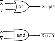
A CMOL framework for interface between nanoscale memristor crossbars and traditional CMOS components have been suggested in [20].
However, even without these operations, min-max circuits can carry out interesting computations. For instance the bitonic sorting algorithm[21] uses a feed-forward network consisting of circuits computing min and max values. It is able to sort elements in parallel steps. Thus min-max circuits can compute robust statistics of their inputs, such as the median. In particular, median computation can be used for majority vote of a set of binary fuzzy classifiers in the manner of random forests [22], [23, Chapter 15.3].
One caveat is that the circuits listed in Figure 3 compute min and max only approximately. The approximation errors are controlled by the ratio , that we shall call m-efficiency. Experimental devices have been constructed with m-efficiency between 10 and [20]. If the m-efficiency is not large enough, the output of circuits in Figure 3 is
Figure 3 shows the effect of varying m-efficiency on the output from a bitonic sorting network. The picture demonstrates a strong linearization effect of a bitonic network for low values of m-efficiency whose impact fades with increasing m-efficiency.

VI Computation with non-ideal devices
Let us compare the behavior of an ideal bilevel memristor with the behavior of experimentally studied devices, especially memristors. Bilevel resistance is indeed typical for metal oxide devices. (Notable is work of W. Lu [26], who showed that amorphous silicon memristor is capable of maintaining many states between and ). Monoticity assumptions are mildly violated by memristors, perhaps due to multiple mechanisms that play role in their memristive behavior. Better monoticity can be seen for instance in memristors [27, Fig.3] in which simpler mechanisms are expected.
Perhaps the biggest concern raised by experimental data is the exponential dependence of switching time on the applied voltage as seen for instance in [28, Figure 1b), d)]. The figure for instance indicates that it takes longer to switch device with half voltage. If the memristance of the device during that time stayed in the interval then charge that flows under voltage in time interval is between and . Thus these data would imply that m-efficiency of the charge-driven memristor would have to be . The paper does not indicate m-efficiency of the device, but this would be outside of the typical range for a device[27]. A violation of memristor behavior does not necessarily preclude applicability of Theorem 1. For its conclusion to hold, one only needs a weaker condition, namely
- (*)
current/voltage bounded away from zero eventually switches memristance of the device to or depending on its sign
This condition is explicitly stated to hold for memristors in the seminal paper [3, pg. 82].
For practical purposes the exponential switching time means that short application of voltages to circuits in Figure 3 do not necessarily compute and in real time. They compute them, if the previous computation yielded min and max, and the order of operands is again the same. If however the order of operands changes and their difference is small, the memristances may change only partially. Precise dynamics are highly nonlinear [29]. Only repeated applications of the same inputs will eventually cause the circuit to compute the correct result. This can be viewed as a learning process of the fuzzy circuit.
Memristive devices are often driven by voltage pulses above “threshold voltage”. This is an empirically determined amplitude that is known to switch the state of a memristive device (or a complementary resistive switch [17]). This approach is however more suitable for discrete levels of circuit inputs, such as those that appear in classical (non-fuzzy) random forest classifiers.
VII Conclusion
We have shown that properties of memristors can be applied to voltage based fuzzy logic computations. In the near future industry is expected to deliver first commercial circuits using memristors. Memristor circuits may prove to be ideally suited for low power memory storage, signal processing, pattern recognition and other applications. Memristor fuzzy logic circuits complement other suggested uses of memristors, such as CMOL, reconfigurable CMOS circuits, CrossNets and other neural networks [20], [30].
There is another way to look at the results presented in our work. It has been observed that memristive phenomena closely mimic behavior of synapses [26],[31], [18]. Since fuzzy logic arises in quite simple context among memristor circuits, it suggests itself for simulations of behavior of complex biological neural systems.
References
- [1] S. Borkar, A. A. Chien, The future of microprocessors, Communications of the ACM 54 (2011) 67–77, doi:10.1145/1941487.1941507.
- [2]
Disruptive
solutions for energy efficient ict, doi:10.2759/4612.
URL http://cordis.europa.eu/fp7/ict/fet-proactive/docs/shapefetip-wp2011-12-10_en.pdf - [3] D. B. Strukov, G. S. Snider, D. R. Stewart, R. S. Wiliams, The missing memristor found, Nature 453 (2008) 80–83, doi:10.1038/nature06932.
- [4] L. O. Chua, Memristor – the missing circuit element, IEEE Trans. Circuit Theory 18 (5) (1971) 507–519.
- [5] G. Snider, R. Amerson, D. Carter, H. Abdalla, M. S. Qureshi, From synapses to circuitry: Using memristive memory to explore the electronic brain, Computer 11 (2011) 21–28.
- [6] R. Waser, R. Dittmann, G. Staikov, K. Szot, Redox-based resistive switching memories - nanoionic mechanisms, prospects and challenges, Advanced Materials 21 (2009) 2632–2663, doi:10.1002/adma.200900375.
- [7] J. Borghetti, et al., ’memristive’ switches enable ’stateful’ logic operations via material implication, Nature 464 (2010) 873–876, doi:10.1038/nature08940.
- [8] R. Rosezin, E.Linn, C. Kügeler, R. Waser, Crossbar logic using bipolar and complementary resistive switches, IEEE Electron Device Letters 32 (6) (2011) 710–712, doi:10.1109/LED.2011.2127439.
- [9] F. Jiang, B. E. Shi, The memristive grid outperforms the resistive grid for edge preserving smoothing, in: European Conference on Circuit Theory and Design, 2009, pp. 181–184.
- [10]
Y. V. Pershin, M. D. Ventra, Solving mazes with
memristors: a massively-parallel approach.
URL arXiv:1103.0021 - [11] L. A. Zadeh, Fuzzy sets, Information and Control 8 (1965) 338–353.
- [12] P. Shor, Polynomial time algorithms for prime factorization and idscrete logarithms on quantum computer, SIAM Journal on Computing 26 (5) (1997) 1484–1509.
- [13] M. Johnson, et al., Quantum annealing with manufactured spins, Nature (473) (2011) 194–198, doi:10.1038/nature10012.
- [14] Q. Xia, et al., Memristor-cmos hybrid integrated circuits for reconfigurable logic, Nano Lett. 9 (10) (2009) 3640–3645.
- [15] R. Bellman, M. Giertz, On the analytic formalism of the theory of fuzzy sets, Information Sci. 5 (1973) 149–156.
- [16] E. Linn, R. Rosezin, C. Kügeler, R. Waser, Complementary resistive switches for passive nanocrossbar memories, Nature Materials 9 (2010) 403–406, doi:10.1038/nmat2748.
- [17] R. Rosezin, E. Linn, L.Nielen, C. Kügeler, R. Bruchhaus, R. Waser, Integrated complementary resistive switches for passive high-density nanocrossbar arrays, IEEE Electron Device Letters 32 (2) (2011) 191–193, doi:10.1109/LED.2010.2090127.
- [18]
F. Merrikh-Bayat, S. B. Shouraki, Bottleneck of using
single memristor as a synapse and its solution.
URL arXiv:1008.3450v2 - [19] M. Blum, R. Rue, K. Yang, On the complexity of max/min/avrg circuitsCMU SCS Technical Report, CMU-CS-02-11.
- [20] K. K. Likharev, Hybrid cmos/nanoelectronic circuits: Opportunities and challenges, Journal of Nanoelectronics and Optoelectronics 3 (3) (2008) 203–230, doi:10.1166/jno.2008.301.
- [21] K. Batcher, Sorting networks and their applications, in: Proc. AFIPS Spring Joint Comput. Conf., Vol. 32, 1968, pp. 307–314.
- [22] C. Marsala, Data mining with ensembles of fuzzy decision trees, in: IEEE Symposium on Computational Intelligence and Data Mining 2009, 2009, pp. 348–354, doi:10.1109/CIDM.2009.4938670.
- [23] T. Hastie, R. Tibshirani, J. Friedman, Elements of statistical learning, Springer.
- [24] P. Grim, Self-reference and chaos in fuzzy logic, IEEE Transactions on fuzzy systems 1 (4) (1993) 237–253.
- [25] T. Kehagias, K. Vezerides, Computation of fuzzy truth values for the liar and related self-referential systems, J. Mult.-Valued Logic Soft Comput. 12 (5-6) (2006) 539–559.
- [26] S. H. Jo, T. Chang, I. Ebong, B. B. Bhadviya, P. Mazumder, W. Lu, Nanoscale memristor device as synapse in neuromorphic systems, Nano Lett. (2010) 1297–1301Doi: 10.1021/nl904092h.
- [27] J. Yang, et al., High switching endurance in memristive devices, Applied Physics Letters 97.
- [28] G. Medeiros-Ribeiro, F. perner, R. Carter, H. Abdalla, M. D. Pickett, R. S. Williams, Lognormal switching times for titanium dioxide bipolar memristors:origin and resolution, Nanotechnology 22 (2011) 095702, doi:10.1088/0957-4484/22/9/095702.
- [29] S. Yu, J. Liang, Y. Wu, H.-D. P. Wong, Read/write schemes analysis for novel complementary resistive switches in passive crossbar memory arrays, Nanotechnology 21 (2010) 465202, doi:10.1088/0957-4484/21/46/465202.
- [30] K. K. Likharev, Crossnets: Neuromorphic hybrid cmos/nanoelectronic networks, Science of Advanced Materials 3 (10) (2011) 322–331, doi:10.1166/sam.2011.117.
- [31] C. Zamarreno-Ramos, L. A. Camunas-Mesa, J. A. Perez-Carrasco, T. Masquelier, T. Serrano-Gotarredona, B. Linares-Barranco, On spike-timing-dependent-plasticity, memristive devices, and building a self-learning visual cortex, frontiers in neuroscience 5, doi:10.3389/frins.2011.00026.