Pairwise Check Decoding for LDPC Coded Two-Way Relay Block Fading Channels
Abstract
Partial decoding has the potential to achieve a larger capacity region than full decoding in two-way relay (TWR) channels. Existing partial decoding realizations are however designed for Gaussian channels and with a static physical layer network coding (PLNC). In this paper, we propose a new solution for joint network coding and channel decoding at the relay, called pairwise check decoding (PCD), for low-density parity-check (LDPC) coded TWR system over block fading channels. The main idea is to form a check relationship table (check-relation-tab) for the superimposed LDPC coded packet pair in the multiple access (MA) phase in conjunction with an adaptive PLNC mapping in the broadcast (BC) phase. Using PCD, we then present a partial decoding method, two-stage closest-neighbor clustering with PCD (TS-CNC-PCD), with the aim of minimizing the worst pairwise error probability. Moreover, we propose the minimum correlation optimization (MCO) for selecting the better check-relation-tabs. Simulation results confirm that the proposed TS-CNC-PCD offers a sizable gain over the conventional XOR with belief propagation (BP) in fading channels.
Index Terms:
Two-way relaying, block fading channel, LDPC, physical layer network coding, partial decoding, pairwise check decoding, closest-neighbor clustering.I Introduction
Two-way relaying, where two source nodes exchange information with the help of a relay node, has recently gained a lot of research interests [3, 4, 5, 6, 7, 8, 9, 10, 11, 12]. It is shown able to overcome the half-duplex constraint and significantly improve the system spectral efficiency in relay-based cooperative networks. Upon receiving the bidirectional information flows, the relay node combines them together and then broadcasts to the two desired destinations. The operation at the relay resembles network coding [13], a technique originally developed for wireline networks. It is thus often referred to as physical layer network coding (PLNC) [7] or analog network coding (ANC) [8].
Among the various two-way relaying strategies, the two practical and efficient ones are known as amplify-and-forward (AF) and decode-and-forward (DF), similar to those in one-way relaying. Different from one-way relaying, the DF strategy for two-way relaying further includes full DF [14, 15] and partial DF [16, 17, 18]. This is because the combining process operated at the relay is a many-to-one mapping (e.g. ). As a result, it is not necessary for the relay to fully decode the message pair before combining them together. Being a simple realization of partial DF, the denoise-and-forward (DNF) strategy proposed in [19] demonstrates significant performance gain over the full DF. It is also known that partial decoding has the potential to achieve a much larger rate region than full decoding, even though its capacity region is still unknown. Consequently, it remains as a fundamental and challenging task to realize the potential of partial decoding in two-way relay (TWR) channels through practical coding and modulation techniques.
Several works have been reported on the implementations of partial DF for channel-coded TWR systems, and they are also known as joint network-coding and channel-coding (JNCD) design in the literature. An intuitive method is to utilize the fact that the network-coded (eg. XOR or modulo addition) codeword pair is also a valid codeword given the same linear code (e.g. LDPC or Lattice codes) applied at both source codes [20, 21, 22, 23]. In this method, the relay first computes the probability of based on the received superimposed signal during the multiple-access (MA) phase, where and are the symbols after channel coding and modulation from source and source , respectively, and then apply soft-decoding to decode the associated network-coded information symbol pair . We refer to this method as partial DF based on conventional XOR. However, this method discards useful information related to the decoding of the whole packet during the mapping from signal to the probability of . A more advanced partial decoding method is to exploit the Euclidean distance profile of the superimposed symbol pair after going through the noisy channel in the MA phase [24]. The relay first decodes the arithmetic-sum of the coded symbol pair and then map it to for broadcasting. The authors in [24] show that this partial DF method based on arithmetic-sum provides higher decoding gain than the one based on conventional XOR. Note that both aforementioned methods are designed specifically for symmetric and Gaussian channels.
For TWR channel with fading, the conventional XOR does not always work well due to the undesired phase and amplitude offset between the two TWR channels in the MA phase. Authors in [25] therefore proposed an adaptive network coding with respect to the instantaneous channel fading, named as closest-neighbor cluster (CNC) mapping. Compared to the conventional XOR, the CNC mapping obtains a higher end-to-end throughput. To further ensure reliable communication, the authors extended this method for convolutional-coded system in [26] and discussed the code design based on trellis-coded modulation (TCM) [27, Section 8.2]. However, this TCM-based CNC mapping requires to change the coding structure at the two source nodes and switches two transmission protocols (CNC DNF and pseudo AF) in order to exploit the system performance.
In this paper, we propose a new relay channel decoding solution, called pairwise check decoding (PCD), for LDPC coded TWR fading channels. The main idea is to form a check relationship table (check-relation-tab) for the coded symbol pair by taking both the employed LDPC codes and the adaptive PLNC mapping into accounts. The proposed PCD algorithm is universal for any adaptive PLNC mapping and does not require the LDPC codes at the two sources being identical. It offers a practical and efficient approach to realizing the promising DNF TWR strategy with advanced channel coding. With the aim of maximizing the minimum Euclidean distance (MED) between any two codewords, we present a partial decoding method, two-stage CNC with PCD (TS-CNC-PCD), for TWR fading channels. The proposed TS-CNC-PCD is appropriate for any choice of constellation size. Moreover, a kind of correlative rows optimization, named as the minimum correlation optimization (MCO), is proposed for selecting the better check-relation-tabs. Simulation results confirm that the proposed TS-CNC-PCD has significant coding gains over the conventional XOR with belief propagation (BP) decoding algorithm.
The rest of the paper is organized as follows. In Section II, we present the channel coding model for TWR block fading channels. Section III analyzes the lower bound of the outage probability. The design criterion of adaptive codeword mapping is interpreted in Section IV. In Section V, we propose the PCD algorithm in detail. Section VI present a two-stage CNC mapping based on PCD decoding, named as TS-CNC-PCD, in terms of optimizing the MED. The convergence behaviors and the coding gains of the proposed TS-CNC-PCD method are simulated in Section VII. Finally, we conclude the paper in Section VIII.
II Channel coding model for two-way relay fading channels

We consider a TWR fading channel where two source nodes, denoted as and , exchange information with the help of a relay node, denoted as . We assume that all the nodes operate in the half-duplex mode. The channel on each communication link is assumed to be corrupted with block fading and additive white Gaussian noise (AWGN). For simplicity, we also assume the channel gains are reciprocal and unchanged during a whole packet transmission.
The proposed channel coding model is shown in Fig. 1, where the communication takes place in two phases. First, the information packet from each source, denoted as , for , is encoded individually by a traditional LDPC code with parity check matrix . Unlike the existing work, we do not impose the constraint that and must be identical. Instead, we only require that they have the same size and the same location of non-zero elements. We further assume that the encoder is operated in , where . Note that -ary () coding can improve the performance compared with binary coding. More details can be found in [28, 29, 30] and references therein. The encoded packet, , is modulated by using -ary modulation, denoted as , such as -PSK or -QAM, generating , and then transmitted simultaneously to the relay node. The -th symbol of each packet is denoted as , , and , respectively. The superimposed packet received by the relay, denoted as is given by
| (1) |
where denotes the complex-valued channel coefficient of link from node to node , and denotes complex AWGN with variance of node . Therein, .
We assume perfect symbol synchronization at the two sources and perfect channel estimation at the relay. After receiving the superimposed packet, the relay first computes the soft information (e.g. likelihood value) about the codeword after PLNC mapping, denoted as , then applies the proposed PCD to obtain the hard-decision (the details will be presented in Sections V and VI). Here, denotes a kind of adaptive PLNC mapping, which is designed on the codeword pair, and , where is the cardinality of the PLNC mapped symbol , which should be . Note that no full decoding of and is needed as an intermediate step. No extra channel encoding at the relay is needed either. Then, the relay broadcasts the modulated coded symbols of , denoted as , and mapping rule to two source nodes. The received signals at the nodes and are respectively written as
| (2) |
Each source node, say , computes the likelihood of the desired information from the received symbols by using the inverse PLNC mapping rule with the help of its self-information . Lastly, the traditional LDPC decoding algorithm, e.g. BP, is applied, the output of which is the desired information packet . Note that each source node should know the check matrix of the other source.
III Analysis of outage probability
In this section, we derive the system outage probability of TWR fading channel, which serves as a good approximation of the achievable frame error rate (FER) in the limit of infinite block length [31]. Here, the system is said to be in outage if the achievable sum-rate falls below a target. Since the capacity region of two-way relaying with partial decoding is still unknown [16, 17, 18], we resort to the capacity outer bound as follows [15, Theorem 2], based on which a lower bound of the outage probability can be obtained.
| (3) |
where is the time sharing parameter, and denote the instantaneous data rate and channel capacity of the link from node to node , for , respectively.
After simple manipulation of the constraints in (3)11 1 The detailed derivation is similar to that described in [32]., we obtain the following linear inequalities about and
| (4) |
Let us further assume that the TWR channels considered here are reciprocal, i.e. for . From (4), we can easily obtain the upper bound of the maximum sum-rate for the considered TWR channels
| (5) |
which is also given in [19]. Therein, each of the terms , , is the channel capacity of a traditional point-to-point channel with input alphabet and received signal , where and denotes a real- or complex-valued channel coefficient of the link from node to with .
With the further assumption of equiprobable channel inputs, extending the well-known formula for the capacity of continuous-valued Gaussian channels [33, Eqs. 3-5] to the case of block fading channels yields
| (6) |
in bit/channel use. Here, represents expectation over given and , with being an element of the modulated signal sets .
In addition, we denote the target sum-rate of overall system as . In our considered channel coded TWR model, given that the same LDPC code rate, denoted as , and the same constellation are employed by the two source nodes, we have
| (7) |
Then the outage probability can be lower bounded as
| (8) |
which can be easily evaluated by Monte Carlo averaging over the block fading coefficients and the AWGN.
IV Design criterion of
Similar to the uncoded system in [25], a necessary condition for successful decoding at two sources/destinations in coded TWR system is for the adaptive PLNC mapping to satisfy the exclusive law:
| (9) |
Given the above necessary condition, we next discuss the design criterion of to optimize the system error performance. We aim at minimizing the pairwise error probability (PEP) between two distinct codewords and in the MA phase because the MA interference dominates the whole system performance. Therein, and denote the corresponding codewords generated by the and codeword pairs with certain selected PLNC mapping respectively. Note that the PEP considered in this work is defined over codewords, whereas [25] was concerned with the PEP over uncoded symbols. For TWR fading channels, the PEP between and conditioned on the instantaneous channel gain pair is given by [34, p. 265] [27, Section 5.5] [35, Eq. 7] [25, Eqs. 5-6]
| (10) |
where and are the energy per coded symbol and the variance of Gaussian noise at relay node C, respectively. is the -function. represents the squared Euclidean distance between the codewords and and is the function of two channel coefficients given by
| (11) |
In (11), denotes the length of transmitted codewords and
| (12) |
From (10), it is clear that to minimize the pairwise error probability, one should design a mapping rule that can maximize the MED between any pair of codewords (). We denote it as
| (13) |
Note that the optimal strategy of the mapping rule is adaptive with respect to the channel conditions.
V Pairwise check decoding (PCD)
After introducing the design criterion of the adaptive PLNC mapping for coded TWR systems in the previous section, we present a general relay decoding framework, named as pairwise check decoding, for any given in this section.
V-A Check relationship table (check-relation-tab) at relay
It is clear that if the conventional XOR mapping is applied, we can easily construct a virtual parity check matrix for the codeword based on and at the relay and then decode using the traditional BP algorithm [36, 37]. It is because the referred XOR mapping is linear. However, if an adaptive PLNC mapping is applied, which is much more likely to be non-linear, such virtual parity check matrix in explicit form cannot be found. Instead, one has to resort to the constraint relationship regarding the codeword pair. In this subsection, we introduce a so-called check-relation-tab to describe such codeword pair constraints.
At first, we set forth some notations. We assume that two LDPC codes and on are used at the two sources. The two parity check matrices have the same size of and the same locations of non-zero’s, where is the codeword length and is the number of parity check symbols. Let and denote the elements at the -th row and -th column of and , respectively. denotes the set of column locations of the non-zero’s in the -th row; denotes the set of column locations of the non-zero’s in the -th row, excluding location . Likewise, and denotes the set of row locations of the non-zero’s in the -th column and those excluding location . Note that in the following sections the arithmetic operations are all in unless specified otherwise.
V-A1 Check-relation-tab
Considering the encoding characteristics of and , we have the set of parity check equations, for each , as follows:
| (14) |
For each set of the above check equations, we construct one check-relation-tab. The -th check-relation-tab essentially characterizes the joint constraint of the symbol pairs at locations . It consists of two parts, one for virtual encoder, and the other for PCD decoder.
In virtual encoder, without loss of generality, we assume that the symbol pair at a random location is an unknown parity check symbol pair while those at the other non-zero locations are the known information symbol pairs. The parity check symbol pair and the information symbol pair are assumed as the symbol pairs composed of the unknown parity check symbols and the known information symbols respectively. We obtain the possible values for at the given base on (14) through enumerating all values for at locations . Then, the symbol pairs at all locations are mapped to , according to a given PLNC mapping rule . Since the number of symbol pairs mapped to each element may not be the same, the probability of occurrence for each element should be computed separately.
For PCD decoder, without loss of generality, we assume that the element at location is known. That is to say, the set of symbol pairs mapped to is given. Then, we should compute the probability of occurrence for the corresponding possible values at locations , named as weighted factor , by classifying the aforementioned probability of each element which is generated by the virtual encoder.
In the following we shall use a toy example to demonstrate the detailed construction of the check-relation-tab as mentioned above. Consider the two source LDPC codes on with
where the code length is 6 and the row weight and column weight are 3 and 2 respectively.
In order to indicate that our proposed PCD approach can deal with any PLNC mapping under the exclusive law (9), a special non-linear clustering of the codeword pair, denoted as , is considered here and characterized as:
Each symbol pair is mapped to one of the three elements . Here, to avoid confusion, we let indicate the decoding symbols (they are not necessarily equal to broadcasted symbols) during the period of operating PCD algorithm. Such mapping may be appropriate when the channel ratio satisfies and the BPSK modulation is applied at two source nodes.

The corresponding Tanner graph of the virtual LDPC code observed at the relay is shown in Fig. 2. The solid circles and squares denote the check functions at each source node, while non-solid circles and squares denote the transmitted symbols of a code. In like manner, the solid and non-solid ellipses denote the check functions and the corresponding received symbol pairs. denotes the -th check function of the LDPC code at the node , where .
Next, we will derive the check function of from and using the segmental Tanner graph in Fig. 2, which is separated from the panoramic Tanner graph. denotes the symbol pair , for . Then, the first set of constraint equations associated with the row of and can be written as:
| (15) |
Given the mapping, the so-called check-relation-tabs for virtual encoder and PCD decoder are generated, as shown in Table I. For virtual encoder, without loss of generality, we assume that the symbol pairs and have been known, e.g. and , as shown in Fig. 2. The possible value for the parity check symbol pair can be obtained by (15). It is important to note that each element constrained by the pairwise check functions corresponds to one symbol pair in , the range of which is in .
| Virtual Encoder | PCD Decoder | ||||||||
| a | (0,1) | a | (0,1) | 1b | (0,0) | a | 0.5 | a | b |
| a | (0,1) | b | (0,0) | 0.5a | (0,1) | a | 0.5 | b | a |
| (1,1) | 0.5c | (1,0) | a | 0.5 | b | c | |||
| a | (0,1) | c | (1,0) | 1b | (1,1) | a | 0.5 | c | b |
| b | (0,0) | a | (0,1) | 0.5a | (0,1) | b | 1 | a | a |
| (1,1) | 0.5c | (1,0) | b | 1 | a | c | |||
| b | (0,0) | b | (0,0) | 1b | (0,0) | b | 1 | b | b |
| (1,1) | (1,1) | (1,1) | b | 1 | c | a | |||
| b | (0,0) | c | (1,0) | 0.5a | (0,1) | b | 1 | c | c |
| (1,1) | 0.5c | (1,0) | c | 0.5 | a | b | |||
| c | (1,0) | a | (0,1) | 1b | (1,1) | c | 0.5 | b | a |
| c | (1,0) | b | (0,0) | 0.5a | (0,1) | c | 0.5 | b | c |
| (1,1) | 0.5c | (1,0) | c | 0.5 | c | b | |||
| c | (1,0) | c | (1,0) | 1b | (0,0) | ||||
Through reverse derivation, the check-relation-tab for PCD decoder are given. Therein, is the weighted factor which should be multiplied with the probability of the two elements behind. Then, we just need to compute the probability of occurrence of the corresponding possible values for and one by one. Interestingly, using the binary LDPC codes or the -ary codes with the non-zero elements , we have the same probability distribution of occurrence among for a given PLNC mapping, like .
V-B Pairwise check decoding (PCD) algorithm
After obtaining the check-relation-tabs, the PCD algorithm can be readily carried out. Note that the locations of non-zeros in the -ary LDPC codes used at two source nodes are still valid here. We only change the check functions of symbol pairs from to by the derived check-relation-tab. Define ; . Let denotes the messages to be passed from symbol node to check node ; denotes the messages to be passed from check node to symbol node . Suppose that , denote the index-set of rows, which have the same target value in the check-relation-tab for PCD decoder. Therein, the element at is generated as and means the index of row.
For a given PLNC mapping , we compute for each that satisfies .
1. Initialization
Compute the initial value of each and each as:
| (16) |
where is the probability of given is received. Obviously, we have even if For example, given mapping22 2 Note that the definition of mapping, which will be used as an example in this subsection, is similar to the definition described in Subsection V-A1., we have
| (17) |
2. First half round iteration: from symbol node to check node
| (18) |
where denotes that of is the designated elements at the -th row in the check-relation-tab for PCD decoder. For mapping, we have
| (19) |
3. Second half round iteration: from check node and initial value to symbol node
| (20) |
where denotes the average probability of occurrence of element and indicates column weight for the -th symbol node. Let , e.g., we have for mapping. Note that in (20) the firstly mentioned denotes the corresponding value generated in Step 1. Here it operates as extra information and takes part in the Tanner graph.
4. Soft decision
| (21) |
Here also denotes the corresponding value generated in Step 1.
5. Hard decision
| (22) |
If satisfies the applied mapping’s check-relation-tab for virtual encoder or the number of iterations exceeds a certain value, then the algorithm stops, otherwise we go to Step 2. Note that mapping denotes the second mapping used in hard decision, which may be different from the mapping applied in soft iterations. Fortunately, the cardinality of the mapping is always far less than that of the mapping. That is to say, the satisfaction of the check-relation-tabs will be checked more effectively. For mapping, mapping is selected as and . Namely, and . Therefore, and should be carried out in hard decision. Therein, denotes the probability of occurrence of the element , and {0,1} indicate the PLNC mapped symbols which will be transmitted in BC phase.
So far, the whole PCD algorithm for arbitrary PLNC mapping is presented.
V-C Convergence behavior
There are many methods that can be used to investigate the convergence behavior of iterative decoding. Examples are the density evolution algorithm [38] and the extrinsic information transfer (EXIT) chart [39], both of which are suitable for LDPC codes over Gaussian channels. However, the virtual LDPC code, namely, check-relation-tab in the considered TWR model is different from conventional LDPC codes. Moreover, the proposed check-relation-tab is determined by the selected PLNC mapping. That is to say, several check-relation-tabs should be selected adaptively at the relay. To the best of our knowledge, there is no any literature to solve the analogous problem up to now. Similar to [24], we resort to simulations in Section VII for confirming the convergence behavior of the proposed PCD algorithm.
V-D Complexity analysis
Since decoding complexity of the proposed PCD approach is basically determined by the generated check-relation-tabs, we focus complexity calculation on the number and size of the check-relation-tabs. Note that the proposed check-relation-tab is generated by certain two correlative rows with the same index of non-zero elements. The two correlative rows is defined as a certain two-rows, in which each row has the same row index of the respective LDPC code, e.g., two rows of and . Let , and denote matrix size, maximum row weight and the -th row weight in degree distributions of an arbitrary irregular LDPC code, respectively. The number of the check-relation-tabs for a given PLNC mapping, denoted as , is upper bounded by
| (23) |
where is a ratio of the number of rows with row weight to . The equality can be reached when the non-zero elements of both two correlative rows are different from each other.
We also obtain the size of the check-relation-tab for virtual encoder with a given PLNC mapping as
| (24) |
where denotes the range of PLNC mapped symbols at the relay, .
Furthermore, the size range of the check-relation-tab for PCD decoder is obtained as
| (25) |
The number and size of the check-relation-tabs are determined by the selected PLNC mapping and the applied optimizations. We will state it in Section VI in detail.
VI Two-stage CNC mapping with PCD
Recall that the design criterion of is to maximize the MED, as stated in Section IV. However, it is difficult to directly maximize the MED. In this section, we shall propose a two-stage CNC mapping based on PCD decoding, which optimizes the symbol distance first and then the Hamming distance.
VI-A Two-stage CNC mapping with PCD (TS-CNC-PCD)
In this method, the traditional CNC mapping proposed in [25] is divided to two steps by a maximum splitting and minimum merging (MSMM) strategy for maximizing the symbol distance first and then a minimum correlation optimization (MCO) method based on the proposed PCD approach is presented to optimize the Hamming distance.
VI-A1 Channel coding structure at the relay
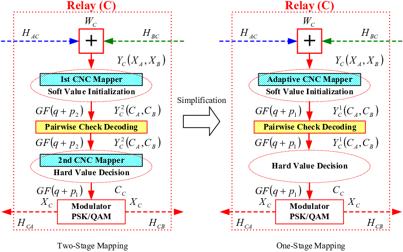
The proposed TS-CNC-PCD is composed of the first CNC mapper (), PCD decoder (), the second CNC mapper () and PSK/QAM modulator as shown in Fig. 3. Upon receiving the superimposed signal, the relay initializes the soft value for PCD decoder by taking into account the 1st CNC mapping. The output of the PCD decoder, i.e., the 2nd CNC mapped codeword packet, , is then modulated to PSK/QAM accordingly to obtain . The cardinality of the received symbol pairs at the relay node is . With the first application of the PLNC which is denoted as the 1st CNC mapping, we reduce the cardinality to by clustering some received symbol pairs into one decoding symbol. Next, we make further reduction in the cardinality through the second application of the PLNC, i.e., the 2nd CNC mapping. Wherein, we cluster some decoding symbols into one broadcasted symbol. Here, both and , , represent the possible expanding of the cardinality compared to . For example, we have , for the QPSK(5QAM) at the relay node when QPSK () is used at two sources. Note that the 1st and 2nd CNC mappings denote the symbol pair mappings while the aforementioned mapping indicates the codeword pair mapping.
VI-A2 Two-stage CNC mapping
Since the best CNC mappings for any choice of constellation size have been presented in [25], we just use for reference and generate the two-stage CNC mapping. Replacing by , we can easily obtain the best CNC mappings for -ary modulations using the Algorithm 1 in [25]. We enlarge the MED between two distinct codewords (e.g. and ) by extending the symbol distance between two individual coded symbols (namely CNC mapped clusters), if the codewords are considered instead of uncoded symbols. Using the proposed MSMM strategy, we divide the traditional CNC mapping (denoted as ) into the 1st CNC mapping (denoted as ) and the 2nd CNC mapping (denoted as ) for soft value initialization and hard value decision, respectively. For certain and , the proposed MSMM strategy is formulated as
a) Maximum splitting (): Any two symbol pairs, belonged to a mapped cluster, should be split into two mapped clusters, if the distance between which is greater than . All mapped clusters, split from an identical mapping, generate a mapping. Note that two distinct mappings can generate an identical mapping for the same channel condition, while an identical mapping can be divided into more than one distinct mappings for different channel conditions.
b) Minimum merging (): Any two distinct mapped clusters, split from a mapped cluster, should be merged into a mapped cluster. All mapped clusters, merged by an identical mapping, generate a mapping. Any two distinct mappings also should be merged into one mapping if the minimum distances of which are both equal to .
Therein, and denote the maximum and minimum values among whole distances between any two mapped clusters, respectively. A mapping is composed by several clusters. Several symbol pairs form a cluster.


| Cardinality | |||||||||||||||||
|---|---|---|---|---|---|---|---|---|---|---|---|---|---|---|---|---|---|
| 9 | |||||||||||||||||
| 9 | |||||||||||||||||
| 4 | |||||||||||||||||
| 9 | |||||||||||||||||
| 9 | |||||||||||||||||
| 4 | |||||||||||||||||
| 12 | |||||||||||||||||
| 12 | |||||||||||||||||
| 5 | |||||||||||||||||
| 12 | |||||||||||||||||
| 12 | |||||||||||||||||
| 5 | |||||||||||||||||
| 12 | |||||||||||||||||
| 12 | |||||||||||||||||
| 5 | |||||||||||||||||
| 12 | |||||||||||||||||
| 12 | |||||||||||||||||
| 5 |

For instance, we consider the 4-ary LDPC codes with the QPSK modulation. The corresponding best CNC mappings have been presented in the Table I in [25]. As depicted in Fig. 4 and Table II, we generate 12 1st CNC mappings and 6 2nd CNC mappings, denoted as and . Take Fig. 5-Case I for example, we have four clusters according to the Table I in [25], e.g., symbol pairs should be clustered together. However, in two-stage CNC mapping, we only group together some symbol pairs (e.g. (0,1) and (1,0) in ) due to that the distance between which is much smaller than . Whereas, we classify the other symbol pairs (e.g. (2,3) and (3,2)), which are more far away from (0,1) or (1,0), into another independent cluster. It is because that the distance between these two clusters {(2,3),(3,2)} and {(0,1),(1,0)} is greater than . Certainly, these separated clusters (e.g. (0,1),(1,0),(2,3) and (3,2)) are merged to one cluster again in . Similarly, / and / are generated according to the proposed MSMM strategy as depicted in Fig. 5-Cases II and III. Here, to avoid confusion, we let indicate the broadcasted symbols , which are not same as the decoding symbols during the period of operating PCD algorithm.
VI-A3 Check-relation-tabs and TS-CNC-PCD
Note that only the 1st CNC mappings are operated before soft iteration in the proposed PCD approach, we just need to generate the check-relation-tabs according to . However, the additional check-relation-tabs for also need to be generated if the satisfaction of the check-relation-tabs should be checked during each iteration. Similar to Subsection V-A and V-B, we can obtain the check-relation-tabs for all 1st and 2nd CNC mappings easily and operate the proposed PCD algorithm directly, although we should modify the cardinality of the designed PLNC mapping here compared with that of Section V.
For instance, we have if the 4-ary LDPC codes and the QPSK modulation are applied at two source nodes. Take the mapping of Table II for example, which is displayed in Fig. 5-Case III. Each symbol pair is mapped to one of 12 elements based on the fading conditions . All the possible mappings are listed below:
Each element constrained by the check functions corresponds to one symbol pair in , the range of which is in . According to the 2nd CNC mapping , we should operate in hard decision.
VI-B Minimum correlation optimization (MCO)
Due to the irregular cardinality of the 1st CNC mappings, the size of mostly generated check-relation-tabs for PCD decoder can approach the maximum value, i.e., . That is to say, we can not obtain larger coding gains from these check-relation-tabs. Note that the check-relation-tabs are fixed once a PLNC mapping and the correlative rows of two LDPC codes ( and ) are all selected. Therefore, a kind of correlative rows optimization, named as the minimum correlation optimization (MCO), is proposed for selecting the better check-relation-tabs.
Using the proposed MCO method (Algorithm 1), we obtain a collection of non-zero elements distributions for certain correlative rows of and . Among these distributions, some special correlative rows like , can generate the check-relation-tabs with a relatively small size. A check-relation-tab with a smaller size always has a lager Hamming distance. Certainly, larger coding gains may be obtained by these check-relation-tabs. Moreover, these special correlative rows can also reduce the number of the check-relation-tabs sharply. In theory, it is likely to generate different check-relation-tabs when the row weight or the non-zero elements of any two rows of each LDPC code are not similar to each other. However, only one check-relation-tab for the virtual encoder and the corresponding one check-relation-tab for PCD decoder needs to be obtained for one or more selected adaptive PLNC mapping when the regular LDPC codes are applied and the non-zero elements in every row follows some special pattens like . Considering the trade-off of complexity and performance, we select the special correlative rows like .
VI-C Simplification of TS-CNC-PCD
To simplify the decoding process, the two-stage CNC mapping can be integrated into one-stage mapping. Specifically, the identical mapping is used for soft value initialization and hard value decision. As shown in Fig. 3, the simplification of TS-CNC-PCD is composed of an adaptive CNC mapper (), PCD decoder () and PSK/QAM modulator. According to the same design principle, we can generate the corresponding check-relation-tabs. The expected error performance may be worse. However, the complexity (size of check-relation-tab) is decreased dramatically. More details can be found in [1, 2].
VII Simulation results
In this section, we present some simulation results to illustrate the convergence behaviors and the coding gains of the proposed PCD approach. For simplicity, each node uses the same transmission power of one unit and observes the same noise power given by . Define an average SNR per information symbol as , where is the channel code rate. According to the proposed MCO method, we generate a 4-ary code from a binary LDPC code ”252.252.3.252”, which is produced by Mackay [40], through replacing by , . Code length, code rate, row weight and column weight are 504, 0.5, 6 and 3, respectively.
The proposed partial decoding method, TS-CNC-PCD, is simulated in kinds of TWR channels. The selections for the two-stage CNC mapping and traditional CNC mapping are based on instantaneous realizations of the channel gain pairs using Fig. 4 (a,b) and Fig. 4 (b), respectively.
For comparison, two benchmark systems are considered. One is the uncoded case, where QPSK modulation is applied and the relay demodulates using different types of PLNC mappings. The other is the coded conventional XOR case, where the same 4-ary LDPC is applied at the source and the relay performs traditional BP decoding with conventional XOR mapping.
VII-A Deterministic channels


Fig. 6 shows the error performance of the proposed PCD algorithm over three deterministic channels whose channel coefficients are fixed. The SER plotted in simulation is defined at the relay node over the MA phase only. The number of maximum iterations is set as 10, 20 and 30. In general, larger maximum iteration leads to better performance for the proposed TS-CNC-PCD method no matter which channel gain pair is considered, as shown in Fig. 6.
In Fig. 6(a) where , it is observed that uncoded XOR and CNC have the same performance. It is because the CNC mapping is degraded to XOR mapping when the two channel gains and are identical. Interestingly, the proposed TS-CNC-PCD is a little bit better than the XOR-BP. Since the traditional XOR can work well in this case, this observation confirms that there is no inherent loss coupling this non-linear operation with a LDPC code (i.e. TS-CNC-PCD) compared to the referred linear operation XOR-BP. Due to that the non-linear operation usually result in shattered pairwise check constraints. In other words, it decreases the Hamming distance of generated codeword space. Fortunately, the proposed TS-CNC-PCD not only compensates the aforesaid performance loss but also obtains extra improvement, through enlarging the cardinality of the decoding symbols and increasing the symbol distance between two distinct PLNC mapped symbols. It is clear that the coding gains of all considered coded systems are more than 3.5dB compared to the uncoded scenarios at SER = .
From Fig. 6(b), we can see that the conventional XOR mapping does not work anymore when and . The reason is that in this case the XOR mapping badly decreases the symbol distance between two distinct PLNC mapped symbols although it has no loss in Hamming distance of generated codeword space. Fortunately, the coding gains of TS-CNC-PCD is also more than 3.5dB compared to the uncoded CNC at SER = .
Lastly, as shown in Fig. 6(c) where and , the XOR-BP coding method outperforms the uncoded CNC more than 1.25dB at SER = while the uncoded XOR mapping still does not work well. At the same time, the proposed TS-CNC-PCD obtains more than 2dB coding gain compared to the XOR-BP at SER = .
In general, our proposed TS-CNC-PCD not only obtains the best performance but also achieves the constant coding gain in considered TWR deterministic channels.
VII-B Block fading channels

Suppose that the channel gains on all links follow Rayleigh distribution and are independent. We assume , where notation denotes expectation function. The black solid lines, denoted as ”Outage Probability”, are actually the lower bound of the outage probability of the TWR block fading channels according to (8). The maximum number of iterations is fixed at 30 for the coded cases.
Fig. 7 shows the frame error rate (FER) performance of the Rayleigh channels. For the uncoded cases, the CNC outperforms the XOR about 4 dB at FER = . At the same FER, the coding gain of the coded XOR is about 8.5 dB. Moreover, the coding gain of the coded CNC is about 6 dB at FER = . The reason that the coding gain of TS-CNC-PCD is less than that of XOR-BP is that the uncoded denoising mapping used at the relay node can eliminate part of the noise, as confirmed in [25]. Nevertheless the TS-CNC-PCD still outperforms the XOR-BP about 2 dB at FER =. At the same time, the gap between the TS-CNC-PCD and the lower bound of the outage probability is 4.5 dB. By any possibility, we can reduce the gaps by increasing the code length.
Lastly, it is important to see that both the relay and the sources obtain the same FER performance. These phenomena confirm that the errors at the relay have severe impact on the performance of whole system. This further confirms the needs for advantage decoding at the relay, such as the proposed PCD algorithm.
VIII Conclusion
In this paper, maintaining the traditional channel coding structure at the two sources, we propose a general relay decoding framework, called pairwise check decoding, or PCD, for any given PLNC mapping. The check-relation-tab for the superimposed LDPC-coded packet pair at relay is formed according to the selected PLNC mapping. Our proposed PCD algorithm is universal for any adaptive PLNC mapping. In order to optimize the MED, we also present a partial decoding method at the relay, TS-CNC-PCD, for LDPC coded TWR block fading channels. Moreover, a check-relation-tab optimization MCO is introduced to improve performance. Simulation results confirm that the proposed TS-CNC-PCD has significant coding gains compared to the conventional XOR with BP and the uncoded system for certain TWR deterministic channels. For TWR fading channels, the TS-CNC-PCD also considerably outperforms the conventional XOR with BP.
References
- [1] J. Liu, M. Tao, Y. Xu, and X. Wang, “Pairwise check decoding for LDPC coded two-way relay fading channels,” in Proc. IEEE Int. Conf. Comm. (ICC), May 2010.
- [2] J. Liu, M. Tao, and Y. Xu, “Pseudo exclusive-or for LDPC coded two-way relay block fading channels,” in Proc. IEEE Int. Conf. Comm. (ICC), June 2011.
- [3] Y. Wu, P. A. Chou, and S.-Y. Kung, “Information exchange in wireless networks with network coding and physical-layer broadcast,” in Proc. Conf. Info. Sci. Sys. (CISS), Mar. 2005.
- [4] P. Larsson, N. Johansson, and K.-E. Sunell, “Coded bi-directional relaying,” in Proc. IEEE Vehi. Tech. Conf. (VTC), May 2006, pp. 851–855.
- [5] P. Popovski and H. Yomo, “Bi-directional amplification of throughput in a wireless multi-hop network,” in Proc. IEEE Vehi. Tech. Conf. (VTC), May 2006, pp. 588–593.
- [6] C. Hausl and J. Hagenauer, “Iterative network and channel decoding for the two-way relay channel,” in Proc. IEEE Int. Conf. Comm. (ICC), June 2006, pp. 1568–1573.
- [7] S. Zhang, S. C. Liew, and P. P. Lam, “Physical-layer network coding,” in Proc. ACM Annual Int. Conf. Mobile Comp. Net. (MobiCom), Sept. 2006, pp. 358–365.
- [8] S. Katti, H. Rahul, W. Hu, D. Katabi, M. M. edard, and J. Crowcroft, “XORs in the air: Practical wireless network coding,” in Proc. ACM Conf. Appl., Tech., Arch., Prot. Comp. Comm. (SIGCOMM), Sept. 2006, pp. 243–254.
- [9] B. Rankov and A. Wittneben, “Spectral efficient protocols for half-duplex fading relay channels,” IEEE J. Sele. Area. Comm., vol. 25, no. 2, pp. 379–389, Feb. 2007.
- [10] L. Song, Y. Li, A. Huang, B. Jiao, and A. V. Vasilakos, “Differential modulation for bidirectional relaying with analog network coding,” IEEE Transactions on Signal Processing, vol. 58, no. 7, pp. 3933–3938, July 2010.
- [11] L. Song, G. Hong, B. Jiao, and M. Debbah, “Joint relay selection and analog network coding using differential modulation in two-way relay channels,” IEEE Transactions on Vehicular Technology, vol. 59, no. 6, July 2010.
- [12] R. Wang and M. Tao, “Joint source and relay precoding designs for mimo two-way relaying based on mse criterion,” IEEE Transactions on Signal Processing, vol. 60, no. 3, pp. 1352–1365, March 2012.
- [13] R. Ahlswede, N. Cai, S.-Y. R. Li, and R. W. Yeung, “Network information flow,” IEEE Trans. Info. Theory, vol. 46, no. 4, pp. 1204–1216, July 2000.
- [14] T. J. Oechtering, C. Schnurr, I. Bjelakovic, and H. Boche, “Broadcast capacity region of two-phase bidirectional relaying,” IEEE Trans. Info. Theory, vol. 54, no. 1, pp. 454–458, Jan. 2008.
- [15] S. J. Kim, P. Mitran, and V. Tarokh, “Performance bounds for bi-directional coded cooperation protocols,” IEEE Trans. Info. Theory, vol. 54, no. 11, pp. 5235–5241, Nov. 2008.
- [16] C. Schnurr, S. Stanczak, and T. J. Oechtering, “Achievable rates for the restricted half-duplex two-way relay channel under a partial-decode-and-forward protocol,” in Proc. IEEE Info. Theory Workshop (ITW), May 2008, pp. 134–138.
- [17] D. Gunduz, E. Tuncel, and J. Nayak, “Rate regions for the separated two-way relay channel,” in Proc. Annual Alle. Conf. Comm. Cont. Comp., Sept. 2008, pp. 1333–1340.
- [18] S. J. Kim, N. Devroye, P. Mitran, and V. Tarokh, “Achievable rate regions for bi-directional relaying,” May 2009. [Online]. Available: http://arxiv.org/abs/0808.0954
- [19] P. Popovski and H. Yomo, “Physical network coding in two-way wireless relay channels,” in Proc. IEEE Int. Conf. Comm. (ICC), June 2007, pp. 707–712.
- [20] W. Nam, S.-Y. Chung, and Y. H. Lee, “Capacity bounds for two-way relay channel,” in Proc. Int. Zurich Seminar Comm. (IZS), March 2008, pp. 144–147.
- [21] B. Nazer and M. Gastpar, “The case for structured random codes in network communication threorems,” in Proc. Info. Theory Workshop (ITW), Sept. 2007.
- [22] K. Narayanan, M. P. Wilson, and A. Sprintson, “Joint physical layer coding and network coding for bi-directional relaying,” in Proc. Alle. Conf. Comm., Cont. and Comp., 2007.
- [23] M. P. Wilson, K. Narayanan, H. Pfister, and A. Sprintson, “Joint physical layer coding and network coding for bi-directional relaying,” IEEE Trans. Info. Theory, vol. 56, no. 11, pp. 5641–5654, Nov. 2010.
- [24] S. Zhang and S.-C. Liew, “Channel coding and decoding in a relay system operated with physical-layer network coding,” IEEE J. Sele. Area. Comm., vol. 27, no. 5, pp. 788–796, June 2009.
- [25] T. Koike-Akino, P. Popovski, and V. Tarokh, “Optimized constellations for two-way wireless relaying with physical network coding,” IEEE J. Sele. Area. Comm., vol. 27, no. 5, pp. 773–787, June 2009.
- [26] ——, “Denoising strategy for convolutionally-coded bidirectional relaying,” in Proc. IEEE Int. Conf. Comm. (ICC), 2009.
- [27] A. Burr, Modulation and Coding for Wireless Communications. Addison-Wesley Longman Publishing Co., Inc., 2001.
- [28] D. Declercq and M. Fossorier, “Decoding algorithms for nonbinary LDPC codes over GF(q),” IEEE Trans. Comm., vol. 55, no. 4, pp. 633–643, April 2007.
- [29] C. Poulliat, M. Fossorier, and D. Declercq, “Design of regular (2, dc)-LDPC codes over GF(q) using their binary images,” IEEE Trans. Comm., vol. 56, no. 10, pp. 1626–1635, October 2008.
- [30] G. Li, I. J. Fair, and W. A. Krzymien, “Density evolution for nonbinary LDPC codes under Gaussian approximation,” IEEE Trans. Info. Theory, vol. 55, no. 3, pp. 997–1015, March 2009.
- [31] E. Biglieri, J. Proakis, and S. Shamai, “Fading channels: information-theoretic and communications aspects,” IEEE Trans. Info. Theory, vol. 44, no. 6, pp. 2619–2692, October 1998.
- [32] J. Liu, M. Tao, and Y. Xu, “Rate regions of a two-way gaussian relay channel,” in Proc. Int. Conf. Comm. Net. China (ChinaCom), Aug. 2009.
- [33] G. Ungerboeck, “Channel coding with multilevel/phase signals,” IEEE Trans. Info. Theory, vol. IT-28, no. 1, pp. 55–67, January 1982.
- [34] J. M. Wozencraft and I. M. Jacobs, Principles of communication engineering. John Wiley & Sons Inc., 1965.
- [35] R. Knopp and P. A. Humblet, “On coding for block fading channels,” IEEE Trans. Info. Theory, vol. 46, no. 1, pp. 189–205, January 2000.
- [36] R. Gallager, “Low-density parity-check codes,” IRE Trans. Info. Theory, pp. 21–28, Jan. 1962.
- [37] T. J. Richardson, M. A. Shokrollahi, and R. L. Urbanke, “Design of capacity-approaching irregular low-density parity-check codes,” IEEE Trans. Info. Theory, vol. 47, no. 2, pp. 619–637, February 2001.
- [38] T. J. Richardson and R. L. Urbanke, “The capacity of low-density parity-check codes under message-passing decoding,” IEEE Trans. Info. Theory, vol. 47, no. 2, pp. 599–618, February 2001.
- [39] S. ten Brink, “Convergence behavior of iteratively decoded parallel concatenated codes,” IEEE Trans. Comm., vol. 49, no. 10, pp. 1727–1737, October 2001.
- [40] D. J. C. Mackay, “Encyclopedia of sparse graph codes,” Sep. 2009. [Online]. Available: http://www.inference.phy.cam.ac.uk/mackay/codes
![[Uncaptioned image]](1106.6174v3/jianquanliu.png) |
Jianquan Liu received the B.S. degree in electronics engineering, and the M.S. degree in communication and information systems from PLA University of Science & Technology (PLAUST), Nanjing, China, in 2000 and 2007, respectively. He is working towards his Ph.D. degree in information and communication engineering at Shanghai Jiao Tong University (SJTU), Shanghai, China. His research interests include Channel Coding, Two-Way Relaying, Physical Layer Network Coding. |
![[Uncaptioned image]](1106.6174v3/meixiatao.png) |
Meixia Tao (S’00-M’04-SM’10) received the B.S. degree in electronic engineering from Fudan University, Shanghai, China, in 1999, and the Ph.D. degree in electrical and electronic engineering from Hong Kong University of Science & Technology in 2003. She is currently an Associate Professor at the Department of Electronic Engineering, Shanghai Jiao Tong University, China. From Aug. 2003 to Aug. 2004, she was a Member of Professional Staff at Hong Kong Applied Science & Technology Research Institute Co. Ltd. From Aug 2004 to Dec. 2007, she was with the Department of Electrical and Computer Engineering at National University of Singapore as an Assistant Professor. Her current research interests include cooperative transmission, physical layer network coding, resource allocation of OFDM networks, and MIMO techniques. Dr. Tao is an Editor for the IEEE WIRELESS COMMUNICATIONS LETTER, and an Associate Editor for the IEEE COMMUNICATIONS LETTERS. She was on the Editorial Boards of the IEEE TRANSACTIONS ON WIRELESS COMMUNICATIONS from 2007 to 2011 and the JOURNAL OF COMMUNICATIONS AND NETWORKS from 2009 to 2011. She served as Track/Symposium Co-Chair for APCC09, ChinaCom09, IEEE ICCCN07, and IEEE ICCCAS07. She has also served as Technical Program Committee member for various conferences, including IEEE INFOCOM, IEEE GLOBECOM, IEEE ICC, IEEE WCNC, and IEEE VTC. Dr. Tao is the recipient of the IEEE ComSoC Asia-Pacific Outstanding Young Researcher Award in 2009. |
![[Uncaptioned image]](1106.6174v3/youyunxu.png) |
Youyun Xu received the Ph.D. Degree in information and communication engineering from Shanghai Jiao Tong University, Shanghai, China, in 1999. He is currently a professor in Nanjing Institute of Communication Engineering, PLA University of Science & Technology (PLAUST), China. He is also a part-time professor with the Institute of Wireless Communication Technologies of Shanghai Jiao Tong University (SJTU), China. He has more than 20-year professional experience of teaching and researching in communication theory and engineering. Now, his research interests are focusing on New Generation Wireless Mobile Communication System (LTE£¬IMT-Advanced and Related), Advanced Channel Coding and Modulation Techniques, Multiuser Information Theory and Radio Resource Management, Wireless Sensor Networks, Cognitive Radio Networks, etc. He is a senior member of the IEEE and a senior member of Chinese Institute of Electronics. |