The UA9 experimental layout
Abstract
The UA9 experimental equipment was installed in the CERN-SPS in March ’09 with the aim of investigating crystal assisted collimation in coasting mode. Its basic layout comprises silicon bent crystals acting as primary collimators mounted inside two vacuum vessels. A movable 60 cm long block of tungsten located downstream at about 90 degrees phase advance intercepts the deflected beam. Scintillators, Gas Electron Multiplier chambers and other beam loss monitors measure nuclear loss rates induced by the interaction of the beam halo in the crystal. Roman pots are installed in the path of the deflected particles and are equipped with a Medipix detector to reconstruct the transverse distribution of the impinging beam. Finally UA9 takes advantage of an LHC-collimator prototype installed close to the Roman pot to help in setting the beam conditions and to analyze the efficiency to deflect the beam. This paper describes in details the hardware installed to study the crystal collimation during 2010.
keywords
Accelerator Subsystems and Technologies; Beam-line instrumentation; Instrumentation for particle accelerators and storage rings - high energy1 Introduction
Halo particles in circular accelerator represent a threat for the good performance, stability and protection of the machine. Specific beam collimation system must be designed and implemented based on passive objects able to scatter and absorb undesired particles. In the last years bent crystals have been efficiently used to extract beam particles out of an accelerator [1, 2, 3] using the coherent interaction of the charged particles with the crystal (crystal channeling). The crystal extraction can be therefore applied to the main beam but also to halo particles[4]. A crystal assisted collimation system for hadron colliders (as the Large Hadron Collider, LHC) has been proposed [5].
A classic two-stage collimation system [6] in accelerators consists of a primary element acting as a small scattering target and a secondary element absorbing particles impinging on it. An amorphous primary target scatters particles in no preferred direction while a bent crystals traps particles with the coherent scattering on aligned atomic planes and kicks them in only one direction. The halo protons can be redirected so that they hit the secondary absorber with a large impact parameter and, Êtherefore, can be efficiently removed.
CERN approved in 2008 the UA9 experiment with the aim of testing directly the crystal assisted collimation as an alternative for both protons and lead ion beam collimation in the LHC. UA9’s final goal is to demonstrate that a crystal based collimation has a higher cleaning efficiency than traditional scheme. This paper therefore focuses on the layout of the UA9 equipment installed in the SPS ring. Various beam instrumentation and detectors are in fact used to measure the beam losses close to the crystal and around the ring with different level of accuracy and redundancy. The procedures to detect and establish the channelling condition and to measure the collimation efficiency are subjects of other publications.
2 The experimental region


The UA9 experiment is installed in the Long Straight Section 5 of the SPS. In this paper we describe the layout that was set in place for the 2010 data-taking apart from small further adjustments of the single components. In Fig.1 the instrumented beam line is shown where the beam cleaning and the losses should be concentrated (the collimation region). Two vacuum vessels are equipped with four silicon crystals mounted on precision goniometers. One tank was manufactured at Institute for High Energy Physics (“IHEP tank”) and the other belonged to the RD22 experiment and was recently refurbished at CERN (“CERN tank”). Inside the CERN tank a tungsten scatterer and a Cherenkov detector are mounted to make direct measurement with an amorphous material and to quantify the number of impinging particles on the crystal 2 (Cr2). Channeled protons are coherently deflected by the angle given by the crystal bending angle (around 100 rad). About 60 m downstream the crystals (position “TACW.51998” ) the channeled protons are displaced by several mm with respect to the primary beam envelope and they are then collected on a secondary tungsten collimator, instrumented with another Cherenkov detector. In close proximity and outside of the vacuum vessels some detectors are installed which are sensitive to the production of secondary particles from inelastic interactions in the obstacles present within the beam pipe. Several scintillators counters equipped with PMTs, Gas Electron Multiplication chambers (GEM) and LHC-type ionization chamber Beam Loss Monitor (LHC BLM) are used for this purpose. About 45 m downstream the crystals a Roman Pot device (RP1, at “XRP.51937”) is installed. It comprises two horizontal axes (H1 and H2 in Fig.1) and each axis supports one Medipix [9] pixel detector that can be moved towards the center of the beam to intercept the channeled beam and to provide an online image of it during data-taking. The detectors are placed in a secondary vacuum vessel that is separated from the primary vacuum by a 0.2 mm thin aluminium layer. Such interface is 3.4 cm thick in the beam direction and could generate secondaries when the vessel is moved into the beam.
A second Roman Pot (at “XRPH.51991”) has been more recently installed; it features four axes (two horizontal and two vertical) and it will be used in the next data taking sessions when detectors are installed inside its four vessels.
Few meters upstream the RP1 a LHC-phase-2 collimator is installed and used to cut portion of the beam and derive measurements of the channeled beam.
In a position that is outside this region and located about 120 m downstream the crystals (at “TAL.52196”, in Fig.2) a 10 cm long duralumin bar is located that is acting as a scraper. This is a dispersive region where the Al bar could intercept off-momentum particles that are likely to be generated in the interaction with the crystals. Here the efficiency of the collimation system can be evaluated by detecting the scattered protons. Scintillators and Cherenkov detectors are installed nearby to intercept the secondary particles produced by the protons inside the Al bar.
SPS was available to UA9 experiment during five dedicated machine development periods lasting 24–48 hours each during the 2010. The machine was operated in coasting mode with one single bunch that at the start of the fill contained about 1011 protons. One crystal at a time was set in such position such that it became the primary collimator and after that measurements could be performed whichÊÊincluded the angular scan of the crystal and scans with various absorbers. In stationary condition protons from the beam halo are diffusing into the edge of the crystal with a rate such that around 100 protons are reaching the crystal at every turn (23 s) within the bunch time length (3 ns). This time structure of the halo protons is reproduced in the signals seen by the various detectors.
2.1 Crystals


The strip-like crystal Cr1 (Fig.3) as well as Cr4 has dimensions mm3 (width height thickness). They fabricated at INFN Ferrara through micromachining techniques with the (110) planes parallel to the largest surfaces [15]. A primary curvature is imparted to bend the strip crystal achieved by the holder design, which result in a secondary curvature due to anticlastic deformation. This secondary deformation is used to steer incoming particles along the 2 mm size. Usage of anticlastic deformation enables to attain a highly uniform bending and to set the metallic components of the holder far from centre of the crystal and in turn far from the beam. The crystal Cr1 has been largely used for channeling and volume reflection studies [16] by the UA9 collaboration and top performed in efficiency (83%) with a low-divergence beam. Bending angle of Cr1 crystal have been characterized by means of white light interferometry (Veeco NT1100) and resulted to be 150 rad, while miscut angle have been measured by means of a Panalytical high resolution X-ray diffractometer and resulted to be about 150 rad. Over a thickness of 2 mm a miscut angle of 100 rad generates a region of reduced channeling efficiency as wide as 0.2 m. For Cr4, the holder has been equipped with a mechanical system to compensate for torsion in the strip crystal thanks to a feedback method during the standard stage of quality check of the crystal at fixed-target experimental area [17]. Crystal miscut resulted to be 20020 rad. Both crystal torsion and bending angle (176 rad) have been measured through deflection under planar channeling regime of a 400 GeV protons beam, available at SPS-H8 line. Crystal torsion, arising as a consequence of holder mechanical imperfections, has been reduced to 0.6 rad/mm.
The quasi-mosaic crystals Cr2 and Cr3 (shown in Fig.4) have been fabricated by Petersburg Nuclear Physics Institute (PNPI). The crystals are deeply polished with submicron abrasive and slow etching: this yields a perfect plane crystalline surface covered by several fine grooves. They have a larger transverse section than strip crystals but similar thickness in the direction parallel to the beam ( mm3 and mm3, respectively). Their bending angles are measured with optical systems to be 150 and 165 rad and their miscut angles are 43 rad and 92 rad respectively. They are installed in rigid holder frames that leave only a fraction of their transverse section to be exposed to the beam ( mm2 and mm2 respectively). Torsional effects induced by the holders have been measured with optical system to be in the range 2–5 rad/mm depending on the vertical position on the crystals.
2.2 Goniometers

In the primary vacuum of CERN tank at “TEC 51795” two high precision goniometers are installed. They allow a linear movement perpendicular to the beam in order to insert the crystals into the beam and they generate a rotation in the horizontal plane. Crystals Cr1 and Cr2 are installed on these two goniometers. In the IHEP tank at “TECS.51793” - that is located 3 m upstream the CERN tank - another mechanical system to which Cr3 and Cr4 are connected is placed in the primary vacuum. In this case the crystals are mounted on two mechanically connected supports that allow horizontal linear movement of each crystal: when one of the crystals is placed at a fixed distance from the beam, it can be rotated by applying a linear movement to the other support. In Fig.5 the series of the two tanks is showed. Both systems can rotate the crystal in angular range of tens of mrad. They were designed to have a resolution (minimum step achievable by the motor) of 1 rad and an accuracy (precision to which the motor goes to a given angular position) close to 10 rad but such performances were only partially reached during data-taking. In all goniometers the linear position of a pushing system (measured with LVDT) is transformed to the crystal angle via a Ògear boxÒ with some error. All goniometers are different but can be characterized by the ratio of the real angular step measured with an optical laser autocollimator (Fig.6) to the value of the step in the motion controller. Such calibration were done in laboratory and directly in situ through optical windows that are available in the CERN and IHEP tank. During angular scan in which the crystal is rotated with a fixed angular velocity (1–10 rad/sec) the angular step calculated from LVDT readings was compared with the average angular step over one second. Average deviations from linearity were measured and accounted for with an ad-hoc model. From the RMS deviation from linearity we estimate an accuracy of 10 rad over an angular range of 15 mrad.

2.3 Absorber
The absorber (at “TACW.51998”) is a 60 cm long tungsten bar (Fig.7) with a cm2 section located in a vacuum tank. It can be moved directly in and out of the beam and therefore acts as secondary collimator in all the measurements performed. Protons generate showers in the material and they can leak out at a level of few per mille. A quartz crystal covering partially the bar entrance face generates Cherenkov light that is transported in the same crystals to a PMT. The light emitted is proportional to the number of crossing protons and can be therefore used to measure the channeling efficiency in this collimation system. The Cherenkov detector signal is acquired and digitized with an amplitude to frequency converter within a gate generated synchronously to the RF SPS signal. This is therefore designed to count protons originated from the single bunch time structure of the beam. Outside the vacuum tank scintillator detectors are installed which are sensitive to secondary particles produced in the hadronic showers and are therefore used to indirectly monitor the channeled beam.

2.4 LHC-type collimator
The LHC-type collimator (“TCSM.51934”) is a full-scale prototype of the LHC Phase II secondary collimator and has two horizontal, one-meter long copper ÒjawsÓ. The position and longitudinal tilt angle of each jaw can be controlled independently by means of four precise stepping motors (two per jaw) with minimum step size of 5 m. The jaw positions are calibrated with respect to the nominal beam center and can be moved across the beam by 5 mm. The maximum collimator gap with fully retracted jaw is 60 mm. The two-sided collimator design allows to precisely define the beam envelope by closing the jaws around the circulating beam orbit and to identify its center. The collimator was also used to scan of the beam deflected by the crystal, in order to measure the channelling efficiency. The protons interacting in the jaws are producing secondaries that are seen by LHC-type beam loss monitors located downstream.
3 Beam loss monitors
Protons circulating in the accelerator hit obstacles and are therefore either deflected, or lose part of their energy or undergo inelastic interactions with nuclei. Detectors sensitive to showers of secondaries produced in such interactions are placed along the beam line to measure the rate of such interaction. We generically indicate them as beam loss monitor (BLM). Different type of detectors were used with different sensitivity to various range of interaction rates.
3.1 Scintillators
Polystirene scintillator slabs with different sizes are mounted outside the beampipe on mechanical supports at critical locations of the layout. They have an approximately cm2 square shape with a thickness of 0.5–1.5 cm. They are readout with conventional photomultipliers (PMT) connected to them via a light guide. Six of them are installed in pairs on the same support in a way coincidence of signals from the two PMTs can be used to suppress low energy background. Two more single scintillator counters are used to monitor indirectly the beam losses. Those scintillators are mostly sensitive to the charged component of the hadronic shower originating from proton interaction in either crystals or collimator jaws. During 2010 data-taking the PMT signals were discriminated with a relatively high threshold corresponding to several minimum ionizing particles (mips) energy release. The discriminated signals were fed into scaler’s channels to count hits in a gate of 20 ms fixed length. The data acquisition system was realized with standard VME protocol in a Labview framework. In the proximity of crystals scintillators counting rates in the crystal amorphous orientation were in the range of 1–10 KHz depending of machine fill conditions. Given the time structure of the beam (one single bunch) several protons are hitting the crystals or other obstacles within few ns. Since no pulse height information is retained scintillators are not able to separate the contribution of the single protons and therefore their counting rate tend to saturate at the machine revolution frequency (43 KHz). They were especially useful during the online data analysis to find the crystals channeling condition and in offline analysis to determine the beam loss patterns in channeling versus amorphous condition.
3.2 PEP-II-type detectors
The PEP-II beam-loss monitors [18] are detecting Cherenkov light using a 16-mm photomultiplier with about 2 ns intrinsic pulse width. The radiator is an 8 mm diameter, 10 mm long fused-silica cylinder placed against the fused-silica PMT window with optical grease on the interface. The opposite end and the cylindrical surface are aluminized for high reflectivity. The assembly is enclosed in 10 mm of lead, originally provided to avoid synchrotron-radiation background in the PEP-II application. The outer shell is a magnetic steel cylinder to provide some shielding against stray magnetic fields. In UA9 the detectors are run at 800 to 900V on the PMT and into a discriminator set to 15 mV. The dark rate is a few counts/min under these conditions. Three detectors of this type were installed along the beam line, a pair of them in the proximity of a SPS collimator (not used during 2010 test) and another close to the tungsten absorber region to monitor the losses downstream the RP1 and the LHC collimator.
3.3 GEM chambers
A triple GEM detector is a micro-pattern gas detector which consists of a primary ionization gap and three consecutive GEM foils [11]. A printed circuit board with readout pads detects the current induced by the drifting electron cloud originating from the last GEM stage. Thus the gas amplification and the signal readout are completely separated. The detectors used in SPS layout are built starting form the standard GEM foils produced by CERN with 1010 cm2 of active area. The anode PCB 1212 cm2 has been designed to house 128 -mm2 pads inside the active area, while keeping eight connectors for the front end electronics (FEE) in the opposite side placed always in the same position. The three foils are successively glued together forming four gaps (3, 1, 2, 1 mm), following the same structure used for the LHCb chambers [12]. The FEE boards used for this development are based on Carioca-GEM Chip [13] (used for LHCb). The boards, designed and realized at LNF, house 16 ASD channels (2 chips) that produce LVDS time over threshold signals. A mother board finally is plugged just on top of the eight boards for low voltage power supply, threshold distribution, and high voltage filters. The LV supply of 2.5 V and the threshold settings are driven through a NIM module that can be set manually or remotely, through a VME programmable DAC (02 V), while the HV is supplied through a module[14] developed at LNF that starting from a 12 V voltage produces the three GEM voltages (0500 V) determining the chamber gain, and the four voltages (01200 V) producing the electric fields for electron cascade drift. The chambers are flushed with a gas mixture ().

Two identical triple GEM detectors are installed on the external walls of the CERN tank (Fig.8), close to the beam pipe with the anode pads perpendicular to the beam direction. They are therefore sensitive to the secondaries produced in the IHEP tank and in the CERN tank. Those detectors are virtually able to count each single charged particle crossing the sensitive volume. Given the relatively small size of each pad, thresholds can be set at the one mip level. Single pad counting rates in amorphous condition were about 1 KHz. Given the lower threshold the GEM detectors were complementary to the scintillators, being more efficient to count particles with relatively lower rates. Anode current readings proportional to the hit rate are used in online monitoring during data-taking and in offline analysis to compare with rates measured by other BLM.
3.4 Medipix

The Medipix2 MXR ASIC[9] is a high spatial, high contrast resolving CMOS pixel read-out chip working in single photon counting mode. It has originally been designed to be combined with different semiconductor sensors segmented into pixels to detect X-rays and used for X-ray and gamma-ray imaging applications. In UA9 it was used to detect the ionization charge released by the proton crossing the silicon pixels. The preamplified signal from each pixel is discriminated to generate one count. The threshold can be adjusted pixelwise with 4 bits for uniform performance of the whole pixel matrix. Counts are accumulated during a predefined exposure time that can be chosen between few tens s to several seconds and data are stored in 13-bit counter per pixel. Read-out is performed at the end of the exposure to avoid dead time. In each of the two arms of RP1 a Medipix detector was installed and used to intercept directly the channeled beam. They have a cm2 active area segmented in -m2 pixels. To avoid dead space the board housing the sensor was cut and the edge of the detector put at 1.53 mm from the internal edge of the thin Al window closing the RP1 vacuum vessel (Fig.9). Energy calibration of such detectors was done using H8 extracted proton beam and sparse data frames (10-s long) with crystal in channeling condition. The mean number of counts per hit is about 1.5 with a large uncertainty (20%). In Fig.10 a Medipix image with Cr1 in channeling condition for the inner Medipix installed in Roman Pot 1 is shown. The frame exposure time was set at 1 sec. The channeled beam is clearly visible and this guided online data-taking. Offline analysis used these frames to compare with beam lifetime to deduce the extraction efficiency[10]. Besides the two detector in RP1, a third Medipix2 detector has been installed outside the beam pipe in order to monitor beam losses in a region downstream the crystals.

3.5 LHC-type BLMs
LHC-type beam loss monitors[19] are ionization chambers with parallel aluminum electrodes separated by 0.5 cm. The detectors are about 50 cm long with a diameter of 9 cm and a sensitive volume of 1.5 liter. The chambers are filled with at 100 mbar overpressure and operated at 1.5 kV. Their counts are integrated over a 1.2 s period.
Eight LHC BLM were installed in various positions of UA9 experimental region. They were especially useful to detect condition of losses characterized by high rates (100 KHz- 1MHz). When UA9 scintillators tend to saturate, LHC BLM are giving a linear response. On the contrary for relatively low rate (few KHz) they do not provide precise measurements.
3.6 SPS devices
Several SPS devices would be available to the UA9 experiment, but they were generally not sensitive to the relatively low current used in the experiment. Some of them were anyway used to measure the beam current and deduce the beam lifetime. BCT were pick-up device detecting an induced current due to the passage of the beam particles. The current is integrated over a 10 ms gate and every 16–18 s the information is readout. The SPS current is derived summing the charge information over 1 sec. From time derivative of this measurement the total loss of protons can be derived with some large uncertainty (20–30%). Morevoer, wire scanners were used to measure the emittance of the beam at each fill.
4 Control software and data acquisition
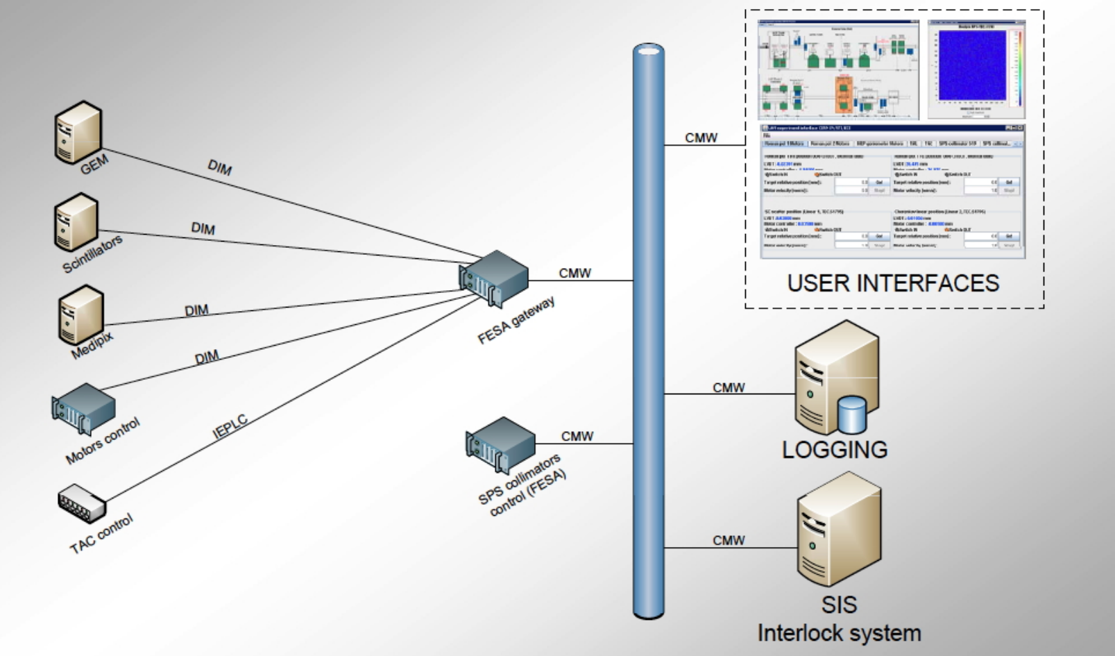
All UA9 devices are controlled via common interface that is able to change positions of the movable devices, to monitor them and to record the rate measurements of the various detectors (Fig.11). A powerful middleware is therefore necessary to bring in a single environment data coming from both the machine control system and the UA9 experimental devices, that have conceptually different low level control electronics. The motorization low-level control is based on Labview real-time PXI chassis that talk to the motor drivers or the LVDT transducers through FPGA cards. All the data from the various devices are in fact coming via different systems and need to be unified and synchronized and then made public over the TCP/IP network (Fig.11). A Distributed Information Management (DIM) system used by LHC experiment and capable to connect to different platform is used to collect and send data to various devices through a Front End System Acquisition Architecture (FESA) gateway. The user can connect to the control system via Java application; positions and detector rates are available online through a graphical interface. Every minute the system saves the whole information into text files and guarantees the synchronization.
5 Summary
In this paper we have described the UA9 experimental layout that has been deployed to study the crystal based collimation in the SPS coasting beam at CERN during 2010. Several high precision movable devices were operated in a vacuum environment to orient crystals in the channeling configuration and to check the deflection of the halo protons far from the primary beam. Beam loss monitors of various types were used to detect secondary particles produced in inelastic interaction of protons with the accelerator apertures. All this system has been operated in several tests in which the channeling condition was established in a very reproducible way.
Acknowledgements.
Work supported by the EuCARD programme GA 227579, within the “Collimators and Materials for high power beams” work package (Colmat-WP8). G. Cavoto and R. Santacesaria acknowledge the support from MIUR (grant FIRB RBFR085M0L 001/I11J10000090001). Some part of this work supported by US DOE under the LARP framework.References
- [1] G. Arduini et al., Phys. Rev. Lett. , 79 (1997) 21, 4182
- [2] A. G. Afonin et al., Nucl. Inst. and Methods B, 234 (2005) 1–2
- [3] N. Doble, L. Gatignon and P. Grafström, Nucl. Instr. and Methods B 119 (1996) 181
- [4] C. T. Murphy et al. Nucl. Instrum. Meth., volume B119; R. A. Carrigan, Jr. et al. Nucl. Instrum. Meth., volume B90 (1994) pages 128Ð132; R. A. Carrigan, Jr. et al. Phys. Rev. ST Accel. Beams, volume 5; R. A. Carrigan, D. Chen, G. Jackson, et al. Phys. Rev. ST Accel. Beams, volume 1(2) (1998) page 022801; R. P. Fliller et al. Phys. Rev. ST Accel. Beams, volume 9 (2006) page 013501
- [5] R. W. Assmann, S. Redaelli, W. Scandale, Optics study for a possible crystal-based collimation system for the LHC, EPAC 06, Edinburgh, June 2006.
- [6] J. B. Jeanneret, Phys. Rev. ST Accel. Beams 1, 081001 (1998)
- [7] R. W. Assmann et al., Designing and Building a Collimation System for the High-Intensity LHC Beam, in PAC03 proceedings.
- [8] W. Scandale et al., Nucl. Inst. and Methods B 268 (2010) 2655
- [9] M. Campbell, 10 years of the Medipix2 Collaboration, Nuclear Instruments and Methods in Physics Research A (2010).
- [10] E. Laface, L. Tlustos, and V. Ippolito, Crystal Collimation efficiency measured with the Medipix detector in SPS UA9 experiment, IPAC 10, Kyoto, Japan.
- [11] F. Sauli, Nucl. Instrum. Meth. A386 (1997) 531–534.
- [12] M. Alfonsi et al., IEEE Transactions on Nuclear Science 53 (2006) 322–325
- [13] W. Bonivento, et al., Nuclear Inst. and Methods A491 (2002) 233–243
- [14] A. Corradi, F. Murtas and D. Tagnani, Nuclear Inst. and Methods A572 (2007) 96–97
- [15] S. Baricordi, et al. App. Phys. Lett. 87/9 (2005); S. Baricordi, et al., J. Phys. D Appl. Phys. 41/24 (2008).
- [16] W. Scandale,et al., Phys. Rev. Lett. 101/16 (2008); W. Scandale, et al. Phys. Lett. B 680/2 (2009) 129; W. Scandale, et al., Phys. Rev. Lett. 101/23 (2008).
- [17] E. Bagli, et al. Proc. IPAC’10, Kyoto, Japan, pp THPEC080
- [18] A. S. Fisher, Instrumentation and Diagnostics for PEP-II’, Proc. 8th Beam Instrumentation Workshop, Stanford, CA, May 4–7, 1998, edited by R. O. Hettel et al., AIP Conference Proceedings 451, Woodbury, New York: 1998, pp. 95–109.
- [19] M.Stockner et al, Proc. DIPAC 2007, Venice, Italy, WEPC09