Optimizing Constellations for Single-Subcarrier Intensity-Modulated Optical Systems
Abstract
We optimize modulation formats for the additive white Gaussian noise channel with nonnegative input, also known as the intensity-modulated direct-detection channel, with and without confining them to a lattice structure. Our optimization criteria are the average electrical, average optical, and peak power. The nonnegative constraint on the input to the channel is translated into a conical constraint in signal space, and modulation formats are designed by sphere packing inside this cone. Some dense packings are found, which yield more power-efficient modulation formats than previously known. For example, at a spectral efficiency of 1.5 bit/s/Hz, the modulation format optimized for average electrical power has a 2.55 dB average electrical power gain over the best known format to achieve a symbol error rate of . The corresponding gains for formats optimized for average and peak optical power are 1.35 and 1.72 dB, respectively. Using modulation formats optimized for peak power in average-power limited systems results in a smaller power penalty than when using formats optimized for average power in peak-power limited systems. We also evaluate the modulation formats in terms of their mutual information to predict their performance in the presence of capacity-achieving error-correcting codes, and finally show numerically and analytically that the optimal modulation formats for reliable transmission in the wideband regime have only one nonzero point.
Index Terms:
Direct detection, fiber-optical communications, free-space optical communications, infrared communications, intensity modulation, lattice codes, mutual information, noncoherent communications, sphere packing.I Introduction
Coherent optical systems, which give access to both the carrier’s amplitude and phase to convey information, allow the design of higher-order modulation formats which offer a good trade-off between spectral and power efficiency. However, in systems where phase information is absent, designing such formats becomes challenging. Examples of such systems include phase-noise limited systems, and noncoherent systems where information is encoded onto the amplitude of the carrier and the envelope of the received signal is detected at the receiver. The latter is prevalent in optical communication systems where the overall cost and complexity is a critical constraint. This type of noncoherent systems is known as intensity-modulated direct-detection (IM/DD) systems and will be the focus of our work. In such systems, the information is encoded onto the intensity of the optical carrier, and this intensity is, at all time instances, nonnegative. Applications using IM/DD are, for example, wireless optical communications [1, 2, 3] and short-haul fiber links used in, e.g., data centers [4, 5].
In the absence of optical amplification, an IM/DD system can be modeled as a conventional additive white Gaussian noise (AWGN) channel whose input is constrained to being nonnegative [1, Ch. 5], [2, 6, 7, 8, 9]. Since the optical phase cannot be used to carry information, resorting to -ary pulse amplitude modulation (-PAM) is a natural low-complexity way of improving the spectral efficiency beyond that of the widespread on-off keying (OOK). However, this is different from the conventional PAM since no negative amplitudes can be used [1, Eq. (5.8)]. In [10, 11], an IM/DD link analysis using -PAM signaling was demonstrated. In [6], upper and lower bounds on the capacity of -, -, -, and -PAM were derived and in [12], the power efficiency of -PAM was shown to be low. The -ary pulse-position modulation (-PPM) formats are known to be power-efficient; however, they suffer from poor spectral efficiency [1, Sec. 5.3.3], [13, 2].
Any nonnegative electrical waveform can be communicated successfully over an IM/DD link. This implies that if the information to be transmitted is modulated on an electrical subcarrier using any -level modulation format, it can be transmitted on an IM/DD link after adding a direct current (DC) bias to ensure its nonnegativity, i.e., the subcarrier amplitude and phase which carry the information can be retrieved at the receiver. This concept is known as subcarrier modulation (SCM) and was described in the wireless infrared communications context [1, Ch. 5]. Therefore, the power efficiency compared to -PAM can be improved since SCM allows the use of power-efficient higher-order modulation formats with IM/DD systems. In [14], the SCM concept was experimentally demonstrated, and in [15] and [16], a novel transmitter design for subcarrier quadrature phase-shift keying (QPSK) and 16-ary quadrature amplitude modulation (16-QAM) was presented. As for the conventional electrical channel, many subcarriers can be superimposed resulting in a frequency division-multiplexing (FDM) system, referred to as multiple-subcarrier modulation (MSM) in the wireless infrared context [1, p. 122], and orthogonal frequency-division multiplexing (OFDM) if the carriers are orthogonal [17]. Further, a subclass of OFDM known as discrete multitone (DMT), where the output of the inverse fast Fourier transform modulator is real instead of complex, was investigated in [18]. In [1, Sec. 5.3.2] and [19], MSM was shown to have poor power efficiency compared to single-subcarrier modulation. Specifically, Barry [1, Sec. 5.3.2] showed that the bandwidth of a multiple-subcarrier system is independent of the number of subcarriers, and that the average optical power penalty for multiple-subcarrier -QAM in comparison with the single-subcarrier case is dB, where is the number of subcarriers. In [20], DMT was shown to suffer considerably in peak-power limited systems. Kang and Hranilovic [21] and You and Kahn [22] proposed techniques to reduce the MSM power penalty.
For single-subcarrier modulation formats, one option is that the DC bias required to ensure the nonnegativity of the electrical waveform does not carry information [1, Ch. 5], [14, 16]. The second option is by allowing the DC bias to carry information, thus potentially improving the power efficiency. This was studied by varying the DC bias on a symbol-by-symbol basis in [23] and within the symbol interval in [22]. By guaranteeing nonnegativity, the investigation of lattice codes for IM/DD with AWGN became feasible [24, 7]. Lattice codes, which are finite sets of points selected out of an -dimensional lattice, have been extensively used in the construction of higher-order modulation formats for AWGN channels with coherent detection [25, 26, 27]. In addition, techniques such as constellation shaping and nonequiprobable signaling have been used to further minimize the average power [26, 28]. In [7], a signal space model for optical IM/DD channels was presented, where average and peak optical power were considered as design constraints for constructing lattice-based modulation formats. Moreover, constellation shaping to reduce the average optical power were studied in [24] for the case where no amplification is used, and in [29] where optical amplifiers are used. An interesting question is if there exist new constellations that perform better than already known ones, with or without coding.
In this work, we address this question by optimizing single-subcarrier modulation formats for uncoded IM/DD systems, with and without confining them to a lattice structure. We choose a uniform probability distribution over constellation points as in [1, 2, 3, 7, 15, 16, 23, 30, 31, 32]. We propose a set of 4-, 8-, and 16-level single-subcarrier modulation formats which are optimized for average electrical, average optical, and peak power. These optimization criteria are all relevant, because the average electrical power is the standard power measure in digital and wireless communications [33, p. 40] and it helps in assessing the power consumption in optical communications [34], while the average optical power is an important figure of merit for skin- and eye-safety measures in wireless optical links [1, Ch. 5], [2, 7] and helps in quantifying the impact of shot noise in fiber-optical communications [35, p. 20]. In addition, the peak power, whether electrical or optical, is relevant for investigations of tolerance against the nonlinearities present in the system [36]. We then analyze the performance of the obtained modulation formats in terms of mutual information at different signal-to-noise ratios (SNR), in order to predict their performance in the presence of capacity-achieving error-correcting codes. Finally, we optimize modulation formats analytically in the wideband regime, i.e., at low SNR, while assuming uniform probability distributions and compare them with other formats.
The remainder of this paper is organized as follows. Section II presents the system model. Section III elaborates on the signal space model, the performance measures, and the single-subcarrier modulation family which is the focus of this work. Section IV explains the optimization criteria that were used and describes the obtained modulation formats. In Section V, we evaluate the performance of these modulation formats in the absence and presence of capacity-achieving error-correcting codes and we compare them with already known modulation formats. In addition, we analytically optimize modulation formats for the low-SNR regime. In Section VI, we summarize the main results and conclusions of this work.
II System Model


The system model under study is depicted in Fig. 1(a). It consists of a modulator which maps the symbol at instant to a waveform belonging to the signaling set , where is the symbol period, is the size of the signaling set, and for where . For the time-disjoint signaling case, the generated waveform
| (1) |
where is an ergodic process uniformly distributed over , is constrained to being real and nonnegative. The received signal can be written as
| (2) |
where is a zero-mean Gaussian process with double-sided power spectral density . It should be noted that there exists no nonnegativity constraint on the signal . This is then followed by the demodulation of which yields , an estimate of . The demodulator is a correlator or matched filter receiver, which minimizes the symbol error rate at a given SNR [33, Sec. 4.1]. This model is different from the conventional AWGN channel by the fact that the input is constrained to being nonnegative.
The baseband model in Fig. 1(a) has been extensively studied in the optical communications context, since it serves as a good model for IM/DD systems [1, Ch. 5], [2, 6, 7, 8, 9], [37, Sec. 11.2.3]. The passband transceiver for IM/DD systems is depicted in Fig. 1(b). In such systems, the electrical nonnegative waveform directly modulates a light source, such as a laser diode. Therefore, the information is carried on the envelope of the passband signal , i.e., the intensity of the optical field, where represents the electro-optical conversion factor in watts per ampere (W/A) [35, 38, 39], is the optical carrier frequency, and is a random phase, uniformly distributed in and slowly varying with . It then propagates through the optical medium depicted as an optical fiber in Fig. 1(b), which could be a free-space optical link in other applications. At the receiver, the photodetector detects the power of . Since the dominant channel impairment in optical IM/DD systems is the thermal noise resulting from the optical-to-electrical conversion [29], [40, p. 155], the received electrical signal can be written as
| (3) |
where is the responsivity of the opto-electrical converter in A/W. Without loss of generality, we set , which yields (2).
III Signal Space Model
By defining a set of orthonormal basis functions for and as in [7], each of the signals in can be represented as
| (4) |
for , where is the vector representation of with respect to the aforementioned basis functions. Therefore, the constellation representing the signaling set can be written as . With this representation, the continuous-time channel models in (2) and (3) can be represented by the discrete-time vector model
| (5) |
where, at instant , is the transmitted vector and is a Gaussian random vector with independent elements, zero mean, and variance per dimension. Since and are both stationary processes, the argument will be dropped from now on. To satisfy the nonnegativity constraint of the channel, the basis function is set as in [6, 7] to
| (6) |
where
This basis function represents the DC bias. Thus, is chosen for each such that
which guarantees the nonnegativity of in (1). The admissible region containing the set of all signal vectors satisfying the nonnegativity constraint can be represented as [7, Eq. (10)]
| (7) |
where . Therefore, the constellation is a finite subset of . The admissible region for IM/DD systems has been shown in [7, Th. 1] to be the convex hull of a generalized -dimensional cone with vertex at the origin and opening in the dimension spanned by .
III-A Performance Measures
Unlike the conventional electrical AWGN channel where the two standard power performance measures are the average and peak electrical power, three important performance measures for IM/DD channels can be extracted from the baseband and passband models in Fig. 1. The first entity is the average electrical power defined as
which for any basis functions can be simplified to
| (8) |
where is the average energy of the constellation, is the expected value, and is a random variable uniformly distributed over . This entity is an important figure of merit for assessing the performance of digital and wireless communication systems [33, p. 40]. Therefore, it is relevant for IM/DD systems for compatibility with classical methods and results [42, 43]. In addition, it helps in quantifying the impact of relative intensity noise (RIN) in fiber-optical links [35], and in assessing the power consumption of optical systems [34]. In [30], was used as a performance measure for comparing different intensity modulation formats.
The second measure is the average optical power , which has been studied in [1, 2, 6, 7, 8] for the wireless optical channel. Limitations are set on for skin- and eye-safety standards to be met. In fiber-optic communications, this entity is used to quantify the impact of shot noise on the performance [35, p. 20]. It is defined as
This measure depends solely on the DC bias required to make the signals nonnegative and can be represented in terms of the symbol period and constellation geometry as [6, 7]
| (9) |
regardless of .
The third measure is the peak optical power defined as
| (10) | |||||
It is relevant for investigations of tolerance against the nonlinear behavior of transmitting and receiving hardware in communication systems [36, 7, 39] and has been studied in [7, 8, 30]. The peak electrical power is directly related to by
and will not be further considered in this paper, since a constellation optimized for will automatically be optimized for too. A general form for as a function of , as in (8) and (9) for and , does not exist, since depends on the exact choice of basis functions. A special case will be studied in Sec. III-B.
To assess the performance of the different modulation formats in the presence of capacity-achieving error-correcting codes, we consider the mutual information [44, Sec. 2.4]
| (11) |
as a performance measure. The terms and are the entropy of and the conditional entropy of given the received vector , averaged over both and . The channel capacity of a discrete memoryless channel is [44, Eq. (7.1)]
| (12) |
where the maximum is taken over all possible input distributions . For a fixed constellation and distribution, the mutual information gives a lower bound on the channel capacity. In our work, like in the works of many other authors, we choose a uniform distribution over the constellation points.
We define as the symbol rate in symbols per second, as the bit rate in bits per second, and as the average energy per bit. Furthermore, in order to have a fair comparison of the bit rates that can be achieved by the different modulation formats in a fixed bandwidth, the spectral efficiency defined as
should be taken into account, where is the baseband bandwidth defined as the first null in the spectrum of . In this paper, we are interested in two extreme cases: the uncoded system, for which , and the system with optimal coding, for which .
III-B Single-Subcarrier Modulation Formats
For in-phase and quadrature phase (I/Q) modulation formats to be used on intensity modulated channels, a DC bias is required in order for to be nonnegative. This could be translated geometrically by having a three-dimensional (3d) Euclidean space spanned by the orthonormal basis functions defined in (6) and
| (13) | |||||
| (14) |
which are the basis functions of conventional I/Q modulation formats such as -PSK and -QAM, where is the electrical subcarrier frequency [7, 1]. As in [1, pp. 115–116] and [7], we use , which is the minimum value for which , , and are orthonormal. In [7], IM/DD modulation formats based on these three basis functions are referred to as raised-QAM, and in [14] as single cycle SCM. At the same symbol rate, modulation formats such as OOK and -PAM have , whereas the modulation formats belonging to the single-subcarrier family occupy ; this is due to the intermediate step of modulating the information onto an electrical subcarrier before modulating the optical carrier [1, Ch. 5], [30].
We now describe explicitly the admissible region for single-subcarrier modulation formats [3, Fig. 4.2], [7].
Theorem 1
Proof:
The admissible region in (7) can be written for single-subcarrier modulation formats as
| (15) |
where
| (16) |
where . Therefore, substituting (16) in (15) yields
| (17) |
which is a 3d-cone with apex angle of pointing in the dimension spanned by , with vertex at the origin. ∎
The average electrical and optical power were given in (8) and (9) as functions of the constellation ; however, the peak optical power defined in (10) could for these basis functions be expressed in terms of the constellation geometry too [3, Fig. 4.3].
Theorem 2
The peak optical power for the single-subcarrier modulation formats with the above defined basis functions can be expressed as
| (18) |
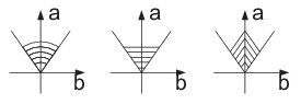
IV Constellation Optimization
To design power-efficient constellations, the admissible region in (17) has to be taken into account. As done before for the conventional AWGN channel [45, 46, 47, 48, 49], our approach of finding the best constellations can be formulated as a sphere-packing problem with the objective of minimizing a cost function depending on the constraints that might be present in the system model shown in Fig. 1. Thus, the optimization problem, for given constants and , can be written as
| Minimize | (19) | ||||
| Subject to | (20) | ||||
| (21) | |||||
| (22) |
where
Choosing the objective function as results in , i.e., a constellation optimized for average electrical power, and results in , i.e., a constellation optimized for average optical power. Finally,
yields , a constellation optimized for peak optical power. Fig. 2 depicts a two-dimensional contour plot of the three objective functions together with the admissible region . The constraint in (21) guarantees that the signals belong to the admissible region , therefore satisfying the nonnegativity criterion of the channel. The minimum distance in (22) serves as a good measure of error probability performance in the presence of AWGN at high SNR. Although this optimization problem is well formulated mathematically, it is difficult to obtain an analytical solution. Therefore, we resorted to numerical optimization techniques as in [45, 46, 47, 48, 49] to find the best constellations. One drawback of such constellations is often the lack of geometric regularity, which increases the modulator and demodulator complexity. The optimization problem is nonconvex; therefore, a local solution does not imply that it is globally optimal.
A special case of this optimization problem, which might not guarantee the optimal solution, is to confine the possible constellations to have a regular structure such as that of a lattice, denoted by . In this case, the above optimization problem can be reformulated by replacing (21) with , and dropping (22) since it is directly inferred by . This was done in [7] for the cubic and Leech lattices. In order to compare with the best nonlattice constellations of relatively small sizes , we use in this work the face-centered cubic lattice (), which provides the densest packing for the 3d-Euclidean space [27, p. xvi]. The obtained lattice-based constellations optimized for average electrical, average optical, and peak optical power are denoted , , and , respectively.
 |
 |
 |
 |
 |
 |
 |
 |
 |
IV-A Optimized Constellations
In Figs. 5–5, the results of the numerical optimizations are illustrated for , , and , for unconstrained sphere packings () and lattice codes (), and for the three power measures. Their coordinates are included in App. A. It should be noted that rotations of all constellations about do not change the power requirements. As we shall see in Sec V, the obtained constellation outperform previously known formats.
IV-A1 -level Constellations
The same 4-level constellation provides the lowest , , and while satisfying the optimization constraints. The geometry of this constellation is a regular tetrahedron where all the spheres, or the constellation points lying at the vertices of this regular tetrahedron, are equidistant from each other. This constellation is also the result of the optimization constrained to , where the apex of the cone coincides with a point in the lattice and the lattice is oriented such that two lattice basis vectors lie in the plane spanned by and . Since the obtained constellation is optimized for , , and , we will refer to it as or .
It is a remarkable fact that the vertex angle of the tetrahedron, defined as the apex angle of the circumscribed cone, is exactly , which is equal to the apex angle of the admissible region . Thus, fits snugly, in the sense that all constellation points are equidistant from each other and lie on the boundary of . For constellation points regarded as unit-diameter spheres, can be illustrated as four spheres touching each other and the boundary of a larger cone as shown in Fig. 5. This, as we shall see in the next section, makes the modulation format very power-efficient. This modulation format consists of a zero-level signal and a biased ternary PSK constellation [50, 51]. In prior work [30], the format was introduced where it was called on-off phase-shift keying (OOPSK), and in [31], it was demonstrated experimentally. Other hybrids between amplitude-shift keying and PSK have been studied in [32] and [52]; however, such modulation formats do not satisfy the nonnegativity constraint of IM/DD channels.
IV-A2 -level Constellations
The highly symmetric and compact constellation consists of four central spheres arranged in a tetrahedron and four additional spheres, each touching three spheres in the central tetrahedron. Surprisingly, seven of the eight spheres touch the conical boundary of . This modulation format is a hybrid between 2-PAM and two ternary PSK constellations, which are DC-biased differently. The constellation is the same as but with the top central sphere moved to the boundary of the admissible region. The constellation optimized for peak optical power, , consists of two tetrahedra lying on top of each other, where one is reflected and rotated about .
On the other hand, when confining the set of points to a lattice structure, the resulting constellations which provide the lowest and are the same, . However, the lattice-based constellation which is optimized for , , is the same as .
IV-A3 -level Constellations
The constellations , , and are not lattice codes; however, the shape obtained could be well justified by the contour plots shown in Fig. 2. The constellation contains the constellations and , whereas consists of two tetrahedra of which one is reflected and eight spheres lying in between, almost at the same level. The presence of two tetrahedra in the constellations optimized for peak optical power, whether 8- or 16-levels, is due to the fact that these constellations are bounded from above by another cone with the same apex angle as that of . This can be inferred from the expression of in (18) [7, Th. 2].
However, when only lattice-based structures are considered, the constellations providing the lowest ,, are the same, i.e., . From Figs. 5–5, it can be noticed that contains both and , and that the constellation is included in all the obtained constellations.
Conjecture 4
For single-subcarrier IM/DD systems, the constellation is included in all optimal constellations with .
IV-B Previously Known Constellations
Our investigation encompasses some previously best known formats, which are presented after being normalized to unit . Readers are referred to [53] for the performance of classical formats such as -PSK and -QAM over IM/DD channels. At spectral efficiency bit/s/Hz (where ), OOK is defined as in terms of .
At spectral efficiency bit/s/Hz, a star-shaped 8-QAM [32] denoted as -QAM, in which the DC bias is allowed to vary from symbol to symbol, is defined as . At spectral efficiency bit/s/Hz, nonnegative -PAM is defined as in terms of , and a version of -QAM denoted as -QAM where the DC bias varies from symbol to symbol, is defined as .
V Performance Analysis
In this section, we assess the performance of all the modulation formats considered in this work in terms of their symbol error rate (SER) performance, asymptotic power gain versus OOK, which was used as a benchmark in [1, 2], and spectral efficiency. Sections V-A–V-B consider uncoded transmission () and Sections V-C–V-D consider coded transmission ().
V-A Symbol Error Rate
 |
 |
 |
For the -level modulation presented in Fig. 5, deriving the exact theoretical SER is not straight-forward, due to the irregularity of the Voronoi regions. However, it has the same structure as the simplex signal set in [33, Sec. 4.1], although it is DC-biased to be used in IM/DD systems. The exact SER of an -ary simplex signal set is [33, Eq. (4.116)]
| (23) |
where is the average symbol energy of the zero-mean simplex constellation and is the Gaussian -function. For , the energy of the zero-mean simplex constellation is , where and are the average symbol and bit energies, respectively, of the constellation. Hence, the exact SER of is
| (24) |
For higher-level modulation formats, the standard union bound found in [33, Eq. (4.81)] is used to approximate the theoretical SER. This union bound can be approximated as
| (25) |
where is the number of distinct signal pairs with for which . This approximation is tight at high SNR.
Fig. 6 (top) shows the simulated and theoretical SER of the studied modulation formats vs. electrical SNR defined as
| (26) |
As expected, all the modulation formats which are optimized for outperform the other formats at the same spectral efficiency. For spectral efficiency bit/s/Hz (blue), has a 0.86 dB average electrical power gain over OOK to achieve . For bit/s/Hz (red), has a 0.31 dB gain over , 0.58 dB gain over , 1.09 dB gain over , and 2.55 dB gain over -QAM to achieve . For bit/s/Hz (black), has a 0.15 dB gain over , 0.47 dB gain over , 0.74 dB gain over , 2.65 dB gain over 4-PAM, and 2.80 dB gain over -QAM. The modulation formats optimized for and are close in performance to those optimized for and to the lattice-based formats.
In order to compare modulation formats in terms of their average optical power requirements, we define the average optical SNR as
| (27) |
in a similar fashion as in [2, Eq. (5)]. Using (8), (9), (26), , and , this expression can be written as
| (28) |
where the first term depends on the regular (electrical) SNR and the second depends only on the constellation geometry. Fig. 6 (middle) shows the SER plotted vs. . Quite obviously, the modulation formats optimized for perform better than the rest. For bit/s/Hz, has a 0.43 dB average optical power gain over OOK to achieve an SER of . For bit/s/Hz, has a 0.04 dB gain over , 0.46 dB gain over , 0.84 dB gain over , and 1.35 dB gain over -QAM to achieve . For bit/s/Hz, has a 0.13 dB gain over , 0.45 dB gain over , 0.66 dB gain over , 1.36 dB gain over -QAM, and 1.44 dB gain over 4-PAM to achieve . It can be noticed that the 8-level modulation formats optimized for average electrical and optical power are very close in performance.
In a similar fashion as , we define the peak optical SNR
| (29) |
in order to assess the different modulation formats under study in terms of their peak optical power requirements. Using (8), (18), (26), , and , this expression can be written as
| (30) |
where the first term depends on the regular (electrical) SNR and the second depends only on the constellation geometry. Fig. 6 (bottom) shows the SER plotted vs. . It is clear that the modulation formats optimized for peak optical power outperform the other formats. For bit/s/Hz, OOK has a 0.82 dB peak optical power gain over to achieve . For bit/s/Hz, has a 0.46 dB gain over , 1.20 dB gain over , 1.25 dB gain over , and 1.72 dB gain over -QAM to achieve an SER of . For bit/s/Hz, has a 0.81 dB peak optical power gain over , 0.98 dB gain over 4-PAM, 1.00 dB gain over , 1.16 dB gain over , and 2.42 dB gain over -QAM to achieve . Overall, modulation formats optimized for perform well in average-power limited systems. In [54], a similar conclusion was reached for the case of coherent optical systems.
 |
 |
 |
V-B Asymptotic Power Efficiency
At asymptotically high SNR, the performance difference in dB between the different modulation formats approaches constant values. We use OOK as a benchmark for power-efficiency on IM/DD channels as in [1, 2].
Fig. 7 (top) presents the average electrical power gain
| (31) |
of a modulation format in comparison to OOK in order to achieve the same error rate performance at asymptotically high SNR, where and are the average electrical power of OOK and the modulation format under study, respectively. For spectral efficiency bit/s/Hz, has a 1.25 dB average electrical power gain over OOK. The overall trend at asymptotically high SNR is similar to the comparison of average electrical SNR in Sec. V-A to achieve . For bit/s/Hz, the 8-level modulation format optimized for , i.e., , has the smallest average electrical power penalty of dB compared to OOK. The asymptotic average electrical power gain of over other formats is larger than the gains at with the exception of having a similar gain when compared to and where both are lattice-based formats. For bit/s/Hz, has a 2.42 dB penalty with respect to OOK at asymptotically high SNR. Its asymptotic electrical power gain is larger than the gains at except when compared to where the gain at asymptotically high SNR is smaller by 0.08 dB.
Fig. 7 (middle) shows the average optical power gain
| (32) |
of the modulation formats under study with respect to OOK at asymptotically high SNR, plotted versus their spectral efficiencies. The average optical power of OOK is , whereas the average optical power of the modulation format under study is denoted as . For bit/s/Hz, offers 0.62 dB average optical power gain over OOK. The asymptotic average optical power gain of over OOK is larger than the gain at in Sec. V-A. For bit/s/Hz, has a 0.71 dB average optical power penalty compared to OOK to achieve the same error rate at asymptotically high SNR. Furthermore, the asymptotic average optical power gains of are larger than the gains when compared with other formats to achieve . Exceptions are when compared to and , where the gains are smaller. Another observation is that the performance of becomes similar to that of . For bit/s/Hz, has a 1.65 dB penalty with respect to OOK at asymptotically high SNR. Compared to the average optical SNR performance gains at , the asymptotic gains are larger except the gain over and .
If peak power is the limiting factor in a communication system, Fig. 7 (bottom) shows the performance of the various modulation formats with respect to their peak optical power gain with respect to OOK
| (33) |
where and denote the peak optical power of OOK and the modulation format under study, respectively. For bit/s/Hz, OOK has the best performance. It has a peak optical power gain of 0.62 dB over . The asymptotic peak optical power gain of OOK compared to is less than the gain in peak optical SNR to achieve . In other words, the peak optical performance of gets closer to OOK at asymptotically high SNR. For bit/s/Hz, has the smallest penalty of 1.51 dB compared to OOK. The asymptotic peak optical power gain of over other formats is larger than the gain reported in Sec. V-A. The exception is the performance of when compared to and , where the asymptotic peak optical power gain is similar to that at . For bit/s/Hz, outperforms the other modulation formats with a penalty of 2.13 dB with respect to OOK at asymptotically high SNR. Even though the asymptotic peak optical power gain of over most other formats is larger than that at , it is smaller when is compared to , , and . So far, all the differences between the gains to achieve and the gains at asymptotically high SNR did not change the order of which formats have a better performance. However, 4-PAM at asymptotically high SNR is now worse than and in terms of peak optical power. Finally, the trend that can be observed in Fig. 7 (bottom) is that the gap in performance between the modulation formats optimized for peak optical power and the rest of the formats under study gets larger with higher spectral efficiencies.
 |
 |
 |
V-C Mutual Information vs. SNR
Fig. 8 depicts the spectral efficiency where of the modulation formats vs. the different SNR measures, i.e., average electrical, average optical, and peak optical SNR. We study the same modulation formats as before, designed to minimize the uncoded SER, although they are now evaluated in a coding context. The mutual information for a fixed constellation and input distribution gives a lower bound on the rate in bits per symbol at which information can be sent with arbitrarily low probability of error, i.e., with the use of optimal coding. Throughout this paper, we consider uniform input distributions.
In Fig. 8 (top), the spectral efficiency is plotted vs. . The best format in terms of is for , for , and for . It is surprising that the formats optimized for outperform the formats optimized for , when compared in terms of . This is different from the uncoded case in Sec. V-A–V-B. The -QAM and formats have a better performance than . Other observations are that outperforms , and 4-PAM has the lowest performance.
In a similar fashion as above, Fig. 8 (middle) shows the spectral efficiency plotted vs. the SNR for the same modulation formats. The best format is for , for , and for . As opposed to the performance vs. , the gap between the formats optimized for average optical power and those for average electrical power is larger. It is interesting that the modulation formats optimized for average optical power perform better than the rest for systems which are limited by either average electrical or optical power.
Fig. 8 (bottom) presents the spectral efficiency vs. . But here, the story is a bit different. The best format is OOK for , and above that. An interesting observation is that 4-PAM performs better than for . Furthermore, modulation formats optimized for peak power perform better in average-power limited systems than when using formats optimized for average power in peak-power limited systems.
V-D Mutual Information in the Wideband Regime
It is apparent from the results in Sec. V-C that constellations optimized for a minimum-distance criterion (i.e., uncoded transmission at high SNR) do not necessarily perform well in terms of mutual information, particularly not in the wideband regime (low spectral efficiency). We define the zero-crossing of a constellation in terms of an SNR measure as the minimum SNR for which . For the three SNR measures considered in this work (, , or ), the zero-crossings will be denoted as , , and , respectively. Fig. 8 shows that in terms of and , and OOK have the same lowest zero-crossing of dB and dB, respectively, among all studied formats. However, OOK has the lowest zero-crossing of 2.21 dB in terms of . The zero-crossings will be explained analytically in this section. An interesting question is if there exist other constellations that perform better in the wideband regime than those found in Sec. IV. As we shall see in this section, the answer is yes.
Theorem 5
For any given with and a uniform input distribution,
| (34) | ||||
| (35) |
| (36) |
Proof:
According to [55, Th. 7], the zero-crossing
| (37) |
where
| (38) |
and is the mean of the constellation. Substituting (38) in (37) yields (34), whereas substituting (34) in (28) and (30) yields (35) and (36), respectively. ∎
The problem of optimizing modulation formats which require the least SNR for reliable communications can be formulated as finding the constellation which provide the minimum zero-crossing . It can be represented mathematically as
| Minimize | (39) | ||||
| Subject to | (41) | ||||
for the three SNR measures considered in this work. Observe that no minimum-distance condition applies. Using [55, Th. 7], this optimization problem can be solved analytically.
Theorem 6
For any given and with ,
| (42) |
with equality if and only if constellation points are at the origin.
Proof:
The numerator of (34) can be bounded using
| (43) | ||||
| (44) |
where for , denotes the inner product, and (44) is due to the fact that
, since from Th. 1, . Equality holds if and only if points are located at the origin. Applying (44) in (34) completes the proof. ∎
Several constellations fulfill Th. 6. If the nonzero constellation point has the coordinates , we refer to this constellation as . At the same symbol rate, occupies a bandwidth of , as OOK and -PAM. However, if the nonzero constellation point is at the surface of , this point has coordinates , and will be referred to as . The constellation belongs to the SCM family; therefore it occupies a bandwidth of , which is twice the bandwidth of OOK and -PAM at the same symbol rate. The reason for choosing the two extremes and is that both have the same ; however, has lower (see Fig. 2) and has lower bandwidth.
Theorem 7
For any given and with ,
| (45) |
with equality if and only if .
Proof:
By using (35), can be bounded by
| (46) | ||||
| (47) | ||||
| (48) |
The inequality in (46) follows from , whereas (47) follows from (44) and (48) follows from the definition of the admissible region in (17). This completes the proof of (45).
To prove that (45) is tight if and only if , we observe that (46) and (47) are tight if and only if points are at the origin, while (48) is tight if and only if all points are located on the boundary of the cone.
∎
So far, we were able to derive optimal constellations in terms of and . For the third SNR measure , however, we resort to a conjecture only, for which we have solid numerical support but no proof.
Conjecture 8
For any ,
| (49) |
with equality if and only if (OOK).
 |
 |
 |
Fig. 9 (top) shows the spectral efficiency in the low regime for and , where , , and . We also include some of the previously optimized constellations for comparison. Even though and , for a given , have the same zero-crossing , performs better at all nonzero spectral efficiencies. Indeed, , , and are the best of all studied constellations for . As , and approach the coherent (non-IM/DD) Shannon limit, i.e., dB.
Fig. 9 (middle) depicts the spectral efficiency in the low regime. For , , and , the formats have lower than ; however, the latter performs better than all other studied formats for . Using (45), approaches as faster for than .
Finally, we show the spectral efficiency in the low regime in Fig. 9 (bottom). Surprisingly, OOK has the best performance up to , and then outperforms the rest. On the other hand, the modulation formats which minimize or do not have the best performance as before. The trend is that their performance is poorer with increased number of levels. Also, is worse than for a given , since the former has a higher peak power requirement due to the nonzero point on the surface of .
It may seem somewhat unexpected that a constellation with points at the origin would perform better at low SNR than all other constellations. Such a constellation is equivalent to a binary constellation with a higher probability for the zero point. Similar constellations were found to achieve capacity in [42] and [56], albeit for different channels. A similar constellation was studied in [57], where a signal set for coherent AWGN channels consisting of two antipodal signals and signals at the origin was used to disprove the strong simplex conjecture, according to which the regular simplex signal set would minimize the uncoded probability of error under an average energy constraint.
VI Conclusions
By using the minimum distance as a modulation design criterion for uncoded systems, we were able to numerically optimize 4-, 8-, and 16-level single-subcarrier IM/DD modulation formats for systems which are limited by average electrical, average optical, and peak power. For , the most power-efficient modulation in terms of average electrical, optical, and peak power has a tetrahedral structure. This constellation is also a subset of all the obtained higher-level constellations. As for the 8- and 16-level constellations, power-efficient schemes are obtained by not confining the set of constellation points to a regular structure such as that of a lattice. However, this comes at the price of losing the geometric regularity, which increases the modulator and demodulator complexity. Our comparisons show that the penalty gap for using modulation formats optimized for in systems which are or limited is much less than the penalty gap when using formats optimized for or in systems which are limited by . Therefore, modulation formats optimized for should be preferred in applications with mixed power requirements. The overall gain of the obtained formats over the previously best known formats is between 0.6 dB and 3 dB at asymptotically high SNR. We conjecture that the new obtained modulation formats are optimal for their size and optimization criteria over uncoded single-subcarrier IM/DD channels.
On the other hand, when capacity-achieving error-correcting codes are deployed, the best modulation formats in the wideband regime (small ) have only one nonzero constellation point. This is confirmed analytically and numerically. At higher , modulation formats optimized for are able to achieve higher reliable transmission rates compared to other formats in systems which are limited by average electrical or optical power. OOK and the 16-level modulation format optimized for peak power offer the best performance in peak-power limited systems. The overall gain of the obtained formats over previously best known formats ranges between 0.3 dB and 1 dB.
Appendix A Obtained Constellations
This appendix lists the coordinates of the numerically optimized constellations in Sec. IV-A. Whenever possible, numerical values have been replaced with the corresponding exact values. Constellations are normalized to unit .
Acknowledgment
The authors would like to acknowledge LINDO Systems for the free license to use their numerical optimization software. We would also like to acknowledge Dr. Giuseppe Durisi and Dr. Alex Alvarado for the interesting discussions about mutual information, Tilak Rajesh Lakshmana for the nice discussions about optimization techniques, and Rajet Krishnan for his comments about the paper structure.
References
- [1] J. R. Barry, Wireless Infrared Communications. Norwell, MA, USA: Kluwer Academic Publishers, 1994.
- [2] J. M. Kahn and J. R. Barry, “Wireless infrared communications,” Proceedings of the IEEE, vol. 85, no. 2, pp. 265–298, 1997.
- [3] S. Hranilovic, Wireless Optical Communication Systems. New York: Springer, 2005.
- [4] S. Randel, F. Breyer, and S. C. J. Lee, “High-speed transmission over multimode optical fibers,” in Proc. Optical Fiber Communication Conference, 2008, p. OWR2.
- [5] D. Molin, G. Kuyt, M. Bigot-Astruc, and P. Sillard, “Recent advances in MMF technology for data networks,” in Proc. Optical Fiber Communication Conference, 2011, p. OWJ6.
- [6] S. Hranilovic and F. R. Kschischang, “Capacity bounds for power- and band-limited optical intensity channels corrupted by Gaussian noise,” IEEE Transactions on Information Theory, vol. 50, no. 5, pp. 784–795, 2004.
- [7] ——, “Optical intensity-modulated direct detection channels: Signal space and lattice codes,” IEEE Transactions on Information Theory, vol. 49, no. 6, pp. 1385–1399, 2003.
- [8] A. A. Farid and S. Hranilovic, “Capacity bounds for wireless optical intensity channels with Gaussian noise,” IEEE Transactions on Information Theory, vol. 56, no. 12, pp. 6066–6077, 2010.
- [9] A. Lapidoth, S. M. Moser, and M. A. Wigger, “On the capacity of free-space optical intensity channels,” IEEE Transactions on Information Theory, vol. 55, no. 10, pp. 4449–4461, Oct. 2009.
- [10] J. E. Cunningham, D. Beckman, X. Zheng, D. Huang, T. Sze, and A. V. Krishnamoorthy, “PAM-4 signaling over VCSELs with 0.13m CMOS chip technology,” Optics Express, vol. 14, no. 25, pp. 12 028–12 038, 2006.
- [11] K. Szczerba, P. Westbergh, J. Karout, J. Gustavsson, Å. Haglund, M. Karlsson, P. Andrekson, E. Agrell, and A. Larsson, “30 Gbps 4-PAM transmission over 200 m of MMF using an 850 nm VCSEL,” Optics Express, vol. 19, no. 26, pp. B203–B208, Dec. 2011.
- [12] S. Walklin and J. Conradi, “Multilevel signaling for increasing the reach of 10 Gb/s lightwave systems,” Journal of Lightwave Technology, vol. 17, no. 11, pp. 2235–2248, 1999.
- [13] S. Hranilovic, “On the design of bandwidth efficient signalling for indoor wireless optical channels,” International Journal of Communication Systems, vol. 18, no. 3, pp. 205–228, 2005.
- [14] A. O. J. Wiberg, B.-E. Olsson, and P. A. Andrekson, “Single cycle subcarrier modulation,” in Proc. Optical Fiber Communication Conference, 2009, p. OTuE1.
- [15] B.-E. Olsson and A. Alping, “Electro-optical subcarrier modulation transmitter for 100 GbE DWDM transport,” in Proc. Asia Optical Fiber Communication and Optoelectronic Exposition and Conference, 2008, p. SaF3.
- [16] B.-E. Olsson and M. Sköld, “QPSK transmitter based on optical amplitude modulation of electrically generated QPSK signal,” in Proc. Asia Optical Fiber Communication and Optoelectronic Exposition and Conference, 2008, p. SaA3.
- [17] J. Armstrong, “OFDM for optical communications,” Journal of Lightwave Technology, vol. 27, no. 3, pp. 189–204, Feb. 2009.
- [18] S. C. J. Lee, F. Breyer, S. Randel, H. P. A. van den Boom, and A. M. J. Koonen, “High-speed transmission over multimode fiber using discrete multitone modulation,” Journal of Optical Networking, vol. 7, no. 2, pp. 183–196, Feb. 2008.
- [19] J. B. Carruthers and J. M. Kahn, “Multiple-subcarrier modulation for nondirected wireless infrared communication,” IEEE Journal on Selected Areas in Communications, vol. 14, no. 3, pp. 538–546, Apr. 1996.
- [20] S. Randel, F. Breyer, S. C. J. Lee, and J. W. Walewski, “Advanced modulation schemes for short-range optical communications,” IEEE Journal of Selected Topics in Quantum Electronics, vol. 16, no. 5, pp. 1280–1289, Sep./Oct. 2010.
- [21] W. Kang and S. Hranilovic, “Optical power reduction for multiple-subcarrier modulated indoor wireless optical channels,” in Proc. IEEE International Conference on Communications, 2006, pp. 2743–2748.
- [22] R. You and J. M. Kahn, “Average power reduction techniques for multiple-subcarrier intensity-modulated optical signals,” IEEE Transactions on Communications, vol. 49, no. 12, pp. 2164–2171, 2001.
- [23] S. Hranilovic and D. A. Johns, “A multilevel modulation scheme for high-speed wireless infrared communications,” in Proc. IEEE International Symposium on Circuits and Systems, 1999, pp. 338–341.
- [24] D.-S. Shiu and J. M. Kahn, “Shaping and nonequiprobable signaling for intensity-modulated signals,” IEEE Transactions on Information Theory, vol. 45, no. 7, pp. 2661–2668, 1999.
- [25] G. D. Forney, Jr., “Coset codes–Part I: Introduction and geometrical classification,” IEEE Transactions on Information Theory, vol. 34, no. 5, pp. 1123–1151, 1988.
- [26] G. D. Forney, Jr. and L.-F. Wei, “Multidimensional constellations–Part I. Introduction, figures of merit, and generalized cross constellations,” IEEE Journal on Selected Areas in Communications, vol. 7, no. 6, pp. 877–892, 1989.
- [27] J. H. Conway and N. J. A. Sloane, Sphere Packings, Lattices and Groups, 3rd ed. New York: Springer-Verlag, 1999.
- [28] A. R. Calderbank and L. H. Ozarow, “Nonequiprobable signaling on the Gaussian channel,” IEEE Transactions on Information Theory, vol. 36, no. 4, pp. 726–740, 1990.
- [29] W. Mao and J. M. Kahn, “Lattice codes for amplified direct-detection optical systems,” IEEE Transactions on Communications, vol. 56, no. 7, pp. 1137–1145, 2008.
- [30] J. Karout, E. Agrell, and M. Karlsson, “Power efficient subcarrier modulation for intensity modulated channels,” Optics Express, vol. 18, no. 17, pp. 17 913–17 921, Aug. 2010.
- [31] K. Szczerba, J. Karout, P. Westbergh, E. Agrell, M. Karlsson, P. Andrekson, and A. Larsson, “Experimental comparison of modulation formats in IM/DD links,” Optics Express, vol. 19, no. 10, pp. 9881–9889, May 2011.
- [32] R.-J. Essiambre, G. Kramer, P. J. Winzer, G. J. Foschini, and B. Goebel, “Capacity limits of optical fiber networks,” Journal of Lightwave Technology, vol. 28, no. 4, pp. 662–701, Feb. 2010.
- [33] M. K. Simon, S. M. Hinedi, and W. C. Lindsey, Digital Communication Techniques: Signal Design and Detection. Englewood Cliffs, NJ: Prentice-Hall, 1995.
- [34] L. P. Chen and K. Y. Lau, “Regime where zero-bias is the low-power solution for digitally modulated laser diodes,” IEEE Photonics Technology Letters, vol. 8, no. 2, pp. 185–187, 1996.
- [35] C. Cox and W. S. C. Chang, “Figures of merit and performance analysis of photonic microwave links,” in RF Photonic Technology in Optical Fiber Links, W. S. C. Chang, Ed. Cambridge University Press, 2002, ch. 1, pp. 1–33.
- [36] B. Inan, S. C. J. Lee, S. Randel, I. Neokosmidis, A. M. J. Koonen, and J. W. Walewski, “Impact of LED nonlinearity on discrete multitone modulation,” Journal of Optical Communications and Networking, vol. 1, no. 5, pp. 439–451, Oct. 2009.
- [37] K.-P. Ho, Phase-Modulated Optical Communication Systems. New York: Springer, 2005.
- [38] P. Westbergh, J. S. Gustavsson, Å. Haglund, A. Larsson, F. Hopfer, G. Fiol, D. Bimberg, and A. Joel, “32 Gbit/s multimode fibre transmission using high-speed, low current density 850 nm VCSEL,” Electronics Letters, vol. 45, no. 7, pp. 366–368, 2009.
- [39] L. A. Coldren and E. R. Hegblom, “Fundamental issues in VCSEL design,” in Vertical-Cavity Surface-Emitting Lasers: Design, Fabrication, Characterization, and Applications, C. W. Wilmsen, H. Temkin, and L. A. Coldren, Eds. Cambridge University Press, 1999, ch. 2, pp. 32–67.
- [40] G. P. Agrawal, Lightwave Technology: Telecommunication Systems. New Jersey: John Wiley & Sons, Inc., 2005.
- [41] B. Goebel, R.-J. Essiambre, G. Kramer, P. J. Winzer, and N. Hanik, “Calculation of mutual information for partially coherent Gaussian channels with applications to fiber optics,” IEEE Transactions on Information Theory, vol. 57, no. 9, pp. 5720–5736, Sep. 2011.
- [42] K.-P. Ho, “Exact evaluation of the capacity for intensity-modulated direct-detection channels with optical amplifier noises,” IEEE Photonics Technology Letters, vol. 17, no. 4, pp. 858–860, Apr. 2005.
- [43] M. S. Moreolo, R. Muñoz, and G. Junyent, “Novel power efficient optical OFDM based on Hartley transform for intensity-modulated direct-detection systems,” Journal of Lightwave Technology, vol. 28, no. 5, pp. 798–805, Mar. 2010.
- [44] T. M. Cover and J. A. Thomas, Elements of Information Theory, 2nd ed. New Jersey: John Wiley & Sons, Inc., 2006.
- [45] G. Foschini, R. Gitlin, and S. Weinstein, “Optimization of two-dimensional signal constellations in the presence of Gaussian noise,” IEEE Transactions on Communications, vol. COM-22, no. 1, pp. 28–38, Jan. 1974.
- [46] J.-E. Porath and T. Aulin, “Design of multidimensional signal constellations,” IEE Proceedings - Communications, vol. 150, no. 5, pp. 317–323, Oct. 2003.
- [47] N. J. A. Sloane, R. H. Hardin, T. D. S. Duff, and J. H. Conway, “Minimal-energy clusters of hard spheres,” Discrete and Computational Geometry, vol. 14, no. 3, pp. 237–259, 1995.
- [48] R. L. Graham and N. J. A. Sloane, “Penny-packing and two-dimensional codes,” Discrete and Computational Geometry, vol. 5, no. 1, pp. 1–11, 1990.
- [49] E. Agrell and M. Karlsson, “Power-efficient modulation formats in coherent transmission systems,” Journal of Lightwave Technology, vol. 27, no. 22, pp. 5115–5126, 2009.
- [50] J. R. Pierce, “Comparison of three-phase modulation with two-phase and four-phase modulation,” IEEE Transactions on Communications, vol. COM-28, no. 7, pp. 1098–1099, 1980.
- [51] N. Ekanayake and T. T. Tjhung, “On ternary phase-shift keyed signaling,” IEEE Transactions on Information Theory, vol. IT-28, no. 4, pp. 658–660, Jul. 1982.
- [52] M. C. Gursoy, “Error rate analysis for peaky signaling over fading channels,” IEEE Transactions on Communications, vol. 57, no. 9, pp. 2546–2550, Sep. 2009.
- [53] J. Karout, “Modulation Optimization for Noncoherent Optical Systems,” Licentiate Thesis (R010/2011), Chalmers University of Technology, Gothenburg, Sweden, 2011.
- [54] M. Karlsson and E. Agrell, “Power-efficient modulation schemes,” in Impact of Nonlinearities on Fiber Optic Communications, S. Kumar, Ed. Springer, 2011, ch. 5, pp. 219–252.
- [55] E. Agrell and A. Alvarado, “Optimal signal sets and binary labelings for BICM at low SNR,” IEEE Transactions on Information Theory, to appear, Jun. 2011, arXiv:1001.4548v2.
- [56] J. G. Smith, “The information capacity of amplitude- and variance-constrained scalar Gaussian channels,” Information and Control, vol. 18, pp. 203–219, 1971.
- [57] M. Steiner, “The strong simplex conjecture is false,” IEEE Transactions on Information Theory, vol. 40, no. 3, pp. 721–731, May 1994.