Coreless vortex dipoles and bubbles in phase-separated binary condensates
Abstract
Vortex dipoles are generated when an obstacle moves through a superfluid. In case of phase-separated binary condensates, with appropriate interaction parameters in pan-cake shaped traps, we show that coreless vortex dipoles are created when a Gaussian obstacle beam traverses across them above a critical speed. As the obstacle passes through the inner component, it carries along a bubble of the outer component. Using Thomas-Fermi approximation, we show that phase-separated binary condensates can either support vortices with empty or filled cores. For time dependent obstacle potentials, ramped down in the present case, relative energy scales of the system influence the dynamical evolution of the binary condensate.
pacs
03.75.Lm,03.75.Kk,03.75.MnVortices are among the most fundamental topological structures in fluid flows. These occur in a variety of fluids at different length scales and in different settings. In Bose-Einstein condensates (BECs), vortices carry integral angular momenta and serve as evidence of superfluidity. Formation and dynamics of solitary and multiple vortices in single species condensates is well studied. These vortices with empty cores and a phase singularity at the center of the cores are normal vortices, whose analogues are found in variety of other fluids. An important development in vortex dynamics is the realization of vortex dipoles, a pair of vortex and anti-vortex, due to superfluid flow past an obstacle [1]. Furthermore, the recent development to observe vortex dipoles in real time [2] opens up the possibility to examine dynamics. The vortex dipoles can also be considered as the embedded section of a vortex ring, which were first observed in BEC as decay product of dark solitons [3]. Another phenomenon in superfluids, where vortex dipoles are crucial is transition to quantum turbulence. The initial requirement is the formation of multiple vortex dipoles, followed by reconnections to form a vortex tangle, which then leads to quantum turbulence [4]. In multi-component condensates, coreless vortices [5] and Skyrmions [6] have been experimentally observed in spinor condensates. Coreless vortices in multi-component spinless condensates are, however, yet to be experimentally realized.
Theoretically, the flow of the miscible binary and spinor condensates across a Gaussian obstacle potential has been investigated [7, 8, 9]. A related work is the seeding of vortex rings when a condensate bubble moves through the bulk of another condensate in binary condensates. This is examined in a recent work [10]. In addition, phase-separated binary condensates, under suitable conditions, are appropriate systems to observe phenomena related to dynamical instabilities. These include, modulational instability [11, 12], Kelvin-Helmholtz instability [13], Rayleigh-Taylor instability [14, 15], countersuperflow instability [16, 17] and Richtmyer-Meshkov instability [18]. Among these, the countersuperflow instability was recently realized experimentally [19]. Phase separation, which has been observed experimentally [20, 21], is also a necessary condition to observe coreless vortex dipoles with a moving obstacle.
In this letter we report the theoretical study of vortex dipole formation when a Gaussian obstacle moves through phase-separated binary condensates. As a specific case, we consider the binary condensate consisting of 85Rb and 87Rb. In this, one of the scattering lengths can be tuned by using magnetic Feshbach resonances [20]. This allows us to choose values of scattering lengths suitable for generation of coreless vortex dipoles.
I Binary condensates and vortex dipoles
Dynamics of weakly interacting binary condensate at zero temperature is well described by a set of coupled GP equations
| (1) |
in mean field approximation, where is the species index. Here , where is the mass and is the -wave scattering length, is the intra-species interaction, , where is the reduced mass and is the inter-species scattering length, is the inter-species interaction, and is the trapping potential experienced by th species. In the present work, we consider binary condensate consisting of 85Rb and 87Rb for which .
Furthermore, we also consider identical trapping potentials, which are axially symmetric, for both the species. The total potential is then
where is the blue detuned Gaussian obstacle potential and is the anisotropy parameter. Define the oscillator length of the trapping potential , and consider as the unit of energy. We can then rewrite the equations in dimensionless form with transformations , and . In pancake-shaped traps (), [22], where is the ground state wave function in axial direction. The Eq. (1) can then be reduced to the two dimensional form
| (2) |
where and . Here we have neglected a constant term corresponding to energy along axial direction as it only shifts the energies and chemical potentials by a constant number without affecting the dynamics. In the present work, we consider so that the ground state of the binary condensate is phase-separated. Geometry of the density distribution is such that the species with the lower repulsion energy forms a core and the other species forms a shell around it. For convenience, we identify the former and later as the first and second species, respectively. With this labelling, interaction energies and for equal populations, this implies .
To be specific, we consider 85Rb-87Rb binary condensate with , , and as the scattering length values and as the number of atoms. Here is tunable with magnetic Feshbach resonance [23]. With these set of parameters, the stationary state of 85Rb-87Rb binary condensate is just phase-separated. The trapping potential and obstacle laser potential parameters are same as those considered in Ref. [1], i.e. Hz, , , , and m. Hereafter we term this set of scattering lengths, number of atoms and trapping potential parameters as set a.
In hydrodynamics, the velocity field of a vortex dipole is the vector sum of two component fields. One of the fields arises due to the inhomogeneous density of the condensate and leads to the precession of an off center vortex around the trap center [25, 24]. In addition to this, each vortex has a velocity field which varies inversely with the distance from its center, which is experienced by the other vortex of vortex dipole. In the present work, we move the obstacle along -axis and generate vortex dipoles located symmetrically about -axis. If and are the locations of the positively and negatively charged vortices of the vortex dipole, respectively, then the velocity field of the positively charged vortex is
where is the rotational frequency of a vortex with charge in the condensate. A similar equation describes the velocity field of the negatively charged vortex.
II Obstacle modified density
To examine the density perturbations from the obstacle beam, let be the radius of the inner species or the interface boundary. And, let be the radial extent of the outer species. In the absence of the obstacle beam, the chemical potential of first and second species in scaled units are and , respectively. The obstacle beam initially () located at traverses towards the center with velocity and the intensity is ramped down at the rate . The location of the beam at a later time is , and intensity of the beam is , where is the initial intensity of the obstacle beam. At the starting point, the total potential and the density of the outer species is zero around the center of the obstacle beam. However, as it traverses the condensates with decreasing intensity, at some later time , . Density is then finite within the obstacle. For compact notations, hereafter we drop the explicit notation of time dependence while writing and .
A critical requirement to form coreless vortices is complete immersion of the obstacle beam within . Based on the previous discussions, as the beam approaches the origin, the last point of contact between the beam and interface at lies along -axis. To determine the condition when complete immersion occurs, consider the total potential along -axis around the obstacle potential
| (3) | |||||
where, the Gaussian beam potential is considered up to the second order term. The expression is appropriate in the neighborhood of the beam, and along -axis it has one local minima ( ) and maxima each. There is also a global minima, however, it is not the correct solution as it lies in the domain where and hence outside the domain of validity of Eq. (3). Correct global minima is located at and is associated with the harmonic potential. The obstacle is considered well immersed when is located at the interfacial radius , and let be the time when it occurs.
When the obstacle beam is well inside the inner species, within the obstacle beam is zero but is nonzero. It then forms a second interface layer, which embeds a bubble of the within . Recollect, the first interface layer is located at and it is where encloses . The second interface, unlike the one at , is a deformed-ellipse and we label it as . Around the interface, the two condensates mix with a penetration depth
and the density of the minority species decays exponentially.
The transition from a single continuous interface to two separate boundaries at and , when the obstacle crosses , is smooth in TF approximation and that is how we have defined . There are, however, strong perturbations when surface tension is considered, and the separation of the two interfaces occurs when the beam is deep inside . Prior to the separation, the interface is deformed to accommodate a long neck region where and are non zero. As the interface splits into two, there are large deformations from the equilibrium interface geometry, and surface tension generates a restoring force to bring it to equilibrium geometry. This creates density patterns with high curvature and initiates formation of the coreless vortex dipoles.
III Obstacle assisted bubble
At a time after the obstacle is immersed in , the location and amplitude of the obstacle potential are
Equilibrium TF within the obstacle potential at this instant of time is
This, however, is higher than the density distribution at , that is as the potential is lower. This is on account of two factors: first, the amplitude of the obstacle potential decreases with time; and second, the harmonic oscillator potential is lower at . The number of atoms, however, does not change from the value at unless there is a strong Josephson current. Density is thus below the equilibrium value once the obstacle beam is well within . This creates a stable bubble of assisted or trapped within the beam and is transported through the .
Departure of from the equilibrium is not the only density evolution within the beam. There is a progressive change of (density of first species within the obstacle beam) as the beam moves deeper into . At time , when the obstacle is completely immersed in the effective potential, experienced by , is larger than . So, is zero within the beam. However, if the rate of ramping is such that at a later time , while the beam is still within , there is a finite within the beam. Since for the condensate, in TF approximation the bulk values of and can not be simultaneously non-zero. At the same time, is forbidden to migrate to the bulk due to the generated potential barrier in the region between interfaces and . To accommodate both and within the beam, the shape of interface is transformed to increase . So that is zero in certain regions within the beam where the condition, , is satisfied. This mechanism is responsible for obstacle assisted transport of across .
IV Energetic stability of normal versus coreless vortex dipoles
We use TF approximation to compare the energetic stabilities of normal and coreless vortex dipoles.
IV.0.1 Normal vortex dipole
Assuming that the vortex affects the density of the condensate only within the core regions, we can adopt the following ansatz for binary condensate with a normal vortex dipole at
| (4) | |||||
| (5) |
The vortex dipole contributes mainly through the kinetic energy of , which may be approximated with the value of single species condensate given in Ref.[26]
| (6) |
where is the coherence length of inner species. Using these ansatz the number of atoms are
| (7) |
In a similar way, we can evaluate the energy of the entire condensate.
IV.0.2 Coreless vortex dipole
For coreless vortex dipole, we adopt the ansatz
| (8) | |||||
| (9) |
Using these ansatz the modified expressions for is
| (10) | |||||
As done earlier, we can also calculate the total energy of the system. The important change in is the inclusion of interface interaction energy . It arises from the interface interactions at the cores of the vortex and antivortex. Based on Ref. [27],
| (11) |
where is the pressure on the circumference of the cores and
| (12) |
In both the case, i.e. with normal and coreless vortex dipoles, the energy can be minimized with the constraint of the fixed number of atoms and as a minimization parameter. For the parameters set a without obstacle potential, the coreless vortex dipole has lower energy than the normal vortex dipole and is shown in Fig. 3 for the vortex dipole located at .
For , , and rest of the parameters same as in parameter set a, condensate with the normal vortex dipole has lower energy than the one with coreless vortex dipole (see Fig. 4). These results are in very good agreement with the numerical results.
V Numerical results and conclusions
To examine the formation of coreless vortex dipoles in finer detail, we resort to numerical solution of Eq. (2) with a modified version of the split-step Crank-Nicholson code reported in Ref. [22]. Consider obstacle potential is initially located in the outer component and is moved across the interface, towards the origin. For this case, we consider 85Rb-87Rb binary condensate with parameters set a, however, with maximum value of obstacle laser potential . The obstacle potential is initially located at . The obstacle moves with the speed of m/s, progressively decreases in strength with rate constant (in scaled units), and vanishes at . The obstacle potential creates a normal vortex dipole as it traverses . As the obstacle penetrates the interface, it carries the vortex dipole generated in the outer component in its region of influence. Further motion of the obstacle, in , creates coreless vortices.
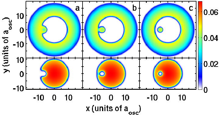
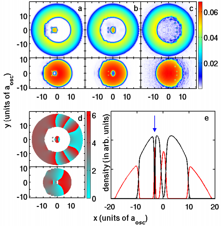
The key factor which influences the generation of coreless vortex dipoles is the deformation at the aft region of the obstacle confined . The deformation accompanied by large mixing is initiated when the interface is about to break up. This is evident even in the stationary state density distribution shown in Fig. 1(b). At break up, the interface repulsion and potential gradient are highest along the -axis and lead to the formation of a dimple. Curvature is large around the deformed interface, and flow of past it generates vortex dipoles. However, as the vortex dipoles are generated within the penetration zone, the build up of around the vortex core drives from the penetration zone to the core of the vortex. For the parameters considered, first coreless vortex dipole is formed soon after the interface break up and is shown in Fig. 2(a) at . The vortex dipole is almost detached when the obstacle reaches origin, shown in Fig. 2(b). From the phase, Fig. 2(d), it is evident that the phase singularity is associated with and is non-zero at the core. This is seen in the plot of densities along a line parallel to -axis and passing through the vortex core, Fig. 2(e). In the figure, the blue arrow marks the location of the vortex core. Another important density modification is, although the obstacle potential is repulsive, has a maxima at the center. This is due to the repulsion energy from . More coreless vortex dipoles are created when the obstacle crosses the center of harmonic potential, 2(c).
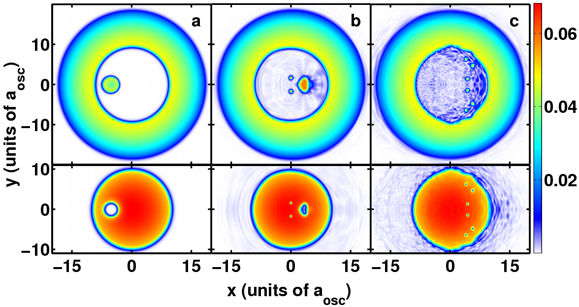
The other initial configuration is to place the obstacle potential within . If is such , then within the obstacle potential is nonzero. Initial density distribution is like in Figs. 1(c) and 5(a). Due to inertia, lags behind the beam when the obstacle suddenly starts to move. When the obstacle has shifted from its initial position to , the points of intersection of the inner interfaces (assumed circular with radii and centered around and ) are
| (13) |
Due to inertia still occupies the region defined as
The potential experienced by along the left interface of decreases as one moves from -axis. This leads to redistribution of in region and creation of a pressure difference at the left bounding arc of . Along this arc, decreases from to and tends to flatten it. Another equally important dynamical process is the redistribution of as increases along the left interface from -axis to . Due to this, start to penetrate the interface from the point where . Thus the repulsive interaction at the interface and gradient of harmonic potential, combine to form a dimple. The dimple formation initiates the formation of (coreless) ghost vortices in the obstacle region [28], which detach to form coreless vortex dipoles as is shown in Figs. 5(b)-(c).
We have studied the motion of the Gaussian obstacle across a phase-separated binary condensate. With the possibility of tuning one of the scattering lengths using Feshbach resonances, these condensates can be used to experimentally realise the obstacle assisted transport of one species across another as well as coreless vortices. Using both TF approximation and exact numerical solutions of coupled GP equations, we have shown that coreless vortex dipoles can be energetically more preferable than normal vortex dipoles.
Acknowledgements.
We thank S. A. Silotri, B. K. Mani, and S. Chattopadhyay for very useful discussions. The numerical computations reported in the paper were done on the 3 TFLOPs cluster at PRL. The work of PM forms a part of Department of Science and Technology (DST), Government of India sponsored research project.References
- [1] T. W. Neely, E. C. Samson, A. S. Bradley, M. J. Davis, and B. P. Anderson, Phys. Rev. Lett. 104, 160401 (2010).
- [2] D. V. Freilich, D. M. Bianchi, A. M. Kaufman, T. K. Langin, and D. S. Hall, Science 329, 1182 (2010).
- [3] B. P. Anderson, P. C. Haljan, C. A. Regal, D. L. Feder, L. A. Collins, C. W. Clark, and E. A. Cornell, Phys. Rev. Lett. 86, 2926 (2001).
- [4] J. A. Seman, et al., arXiv:1007.4953v4.
- [5] A. E. Leanhardt, Y. Shin, D. Kielpinski, D. E. Pritchard, and W. Ketterle, Phys. Rev. Lett. 90, 140403 (2003).
- [6] L. S. Leslie, A. Hansen, K. C. Wright, B. M. Deutsch, and N. P. Bigelow, Phys. Rev. Lett. 103, 250401 (2009)
- [7] H. Susanto, P. G. Kevrekidis, R. Carretero-Gonzalez, B. A. Malomed, D. J. Frantzeskakis, and A. R. Bishop, Phys. Rev. A 75, 055601 (2007).
- [8] Yu. G. Gladush, A. M. Kamchatnov, Z. Shi, P. G. Kevrekidis, D. J. Frantzeskakis, and B. A. Malomed, Phys. Rev. A 79, 033623 (2009).
- [9] A. S. Rodrigues, et al., Phys. Rev. A 79, 043603 (2009).
- [10] K. Sasaki, N. Suzuki, and H. Saito, Phys. Rev. A 83, 033602 (2011).
- [11] K. Kasamatsu, and M. Tsubota, Phys. Rev. Lett. 93, 100402 (2004).
- [12] S. Ronen, J. L. Bohn, L. E. Halmo, and M. Edwards, Phys. Rev. A 78, 053613 (2008).
- [13] H. Takeuchi, N. Suzuki, K. Kasamatsu, H. Saito, and M. Tsubota, Phys. Rev. B 81, 094517 (2010).
- [14] S. Gautam, and D. Angom, Phys. Rev. A 81, 053616 (2010).
- [15] K. Sasaki, N. Suzuki, D. Akamatsu, and H. Saito, Phys. Rev. A 80, 063611 (2009).
- [16] H. Takeuchi, S. Ishino, and M. Tsubota, Phys. Rev. Lett. 105, 205301 (2010).
- [17] N. Suzuki, H. Takeuchi, K. Kasamatsu, M. Tsubota, and H. Saito, Phys. Rev. A. 82, 063604 (2010).
- [18] A. Bezett, V. Bychkov, E. Lundh, D. Kobyakov, and M. Marklund, Phys. Rev. A. 82, 043608 (2010).
- [19] C. Hamner, J. J. Chang, P. Engels, and M. A. Hoefer, Phys. Rev. Lett. 106, 065302 (2011).
- [20] S. B. Papp, J. M. Pino, and C. E. Wieman, Phys. Rev. Lett. 101, 040402 (2008).
- [21] S. Tojo, Y. Taguchi, Y. Masuyama, T. Hayashi, H. Saito, and T. Hirano, Phys. Rev. A 82, 033609 (2010).
- [22] P. Muruganandam, and S. K. Adhikari, Comp. Phys. Comm. 180, 1888 (2009).
- [23] S. L. Cornish, N. R. Claussen, J. L. Roberts, E. A. Cornell, and C. E. Wieman, Phys. Rev. Lett. 85, 1795 (2000).
- [24] A. A. Svidzinsky and A. L. Fetter, Phys. Rev. Lett. 84, 5919 (2000).
- [25] B. Jackson, J. .F. McCann, and C. .S. Adams Phys. Rev. A 61, 013604 (1999).
- [26] Q. Zhou and H. Zhai, Phys. Rev. A 70, 043619 (2004).
- [27] E. Timmermans, Phys. Rev. Lett. 81, 5718 (1998).
- [28] K. Fujimoto and M. Tsubota, Phys. Rev. A 83, 053609 (2011).