Performance of the Fast Beam Conditions Monitor BCM1F of CMS in the first running periods of LHC
Abstract
The Beam Conditions and Radiation Monitoring System, BRM, is implemented in CMS to protect the detector and provide an interface to the LHC. Seven sub-systems monitor beam conditions and the radiation level inside the detector on different time scales. They detect adverse beam conditions, facilitate beam tuning close to CMS, and measure the doses accumulated in different detector components. Data are taken and analysed independently of the CMS data acquisition, displayed in the control room, and provide inputs to the trigger system and the LHC operators. In case of beam conditions dangerous to the CMS detector, a beam abort is induced.
The Fast Beam Conditions Monitor, BCM1F, is a flux counter close to the beam pipe inside the tracker volume. It uses single-crystal CVD diamond sensors, radiation-hard FE electronics, and optical signal transmission to measure the beam halo as well as collision products bunch by bunch. The system has been operational during the initiatory runs of LHC in September 2008. It works reliably since the restart in 2009 and is invaluable to CMS for everyday LHC operation. A characterisation of the system on the basis of data collected during LHC operation is presented.
keywords
Control and monitor systems online; Data acquisition concepts; Radiation-hard electronics1 The CMS Beam Conditions and Radiation Monitoring System, BRM
The Compact Muon Solenoid (CMS) [1] is a multi-purpose detector experiment at interaction point (IP) 5 of the Large Hadron Collider (LHC) at CERN. Beam losses in the LHC may cause serious harm to detector components, so their advent must be detected in order to avert damages of the detector. A monitoring system is needed that allows diagnosis of adverse beam conditions and can initiate beam aborts or shut down vulnerable detectors, if necessary.

Throughout the CMS detector, the beam conditions and the radiation level are monitored by seven sub-systems working on different time scales [2]. Locations of these systems are indicated in Figure 1, and some of their specifications are listed in Table 1 [3]. These systems are operated independently of the LHC power supply and the CMS data acquisition and must be active whenever there might be beam in the LHC.
| Sub-system | Sensor | Location | Time resolution | Function |
|---|---|---|---|---|
| Passives | TLD | in CMS and cavern | long-term | monitoring |
| RADMON | RadFET + SRAM | around CMS | monitoring | |
| BCM2 | pCVD diamond | protection | ||
| BCM1L | pCVD diamond | protection | ||
| BSC | scintillator | monitoring | ||
| BCM1F | sCVD diamond | mon./prot. | ||
| BPTX | beam pickup | monitoring |
2 The Fast Beam Conditions Monitor, BCM1F
Conceptual design
Four modules, consisting of sensor, pre-amplifier, and optical driver, are arranged around the beam pipe on either detector side at distances of from the beam axis and from the IP. They measure the flux of beam halo particles as well as of collision products, thereby providing CMS Background 1 for the LHC control. Particularly radiation-hard components are needed in this situation. Additional requirements are low power dissipation and excellent time resolution in order to detect single relativistic charged particles with a time resolution better than the time between bunch crossings [4].

Readout chain and data acquisition
The sensors are single-crystal chemical vapour deposition (sCVD) diamonds of the size . They are metallised on both sides and operated as solid state ionisation chambers, as illustrated in Figure 2. Charge-sensitive, radiation-hard amplifier ASICs of the type JK16 [5] collect the charges induced and shape proportional signals. These are transmitted to the counting room as optical signals, converted back to electrical signals, and processed and analysed by several back-end components. The analogue signals are fed into a discriminator that supplies scalers and time-to-digital converters (TDC) with logical signals. An analogue-to-digital converter (ADC) samples the input voltages to obtain digitised signal images.
Data acquired by all these readout devices are processed immediately. Relevant results are displayed in the control room and passed on to the central CMS data acquisition. Raw data are stored permanently on disk for offline analyses.
Results obtained with first beams
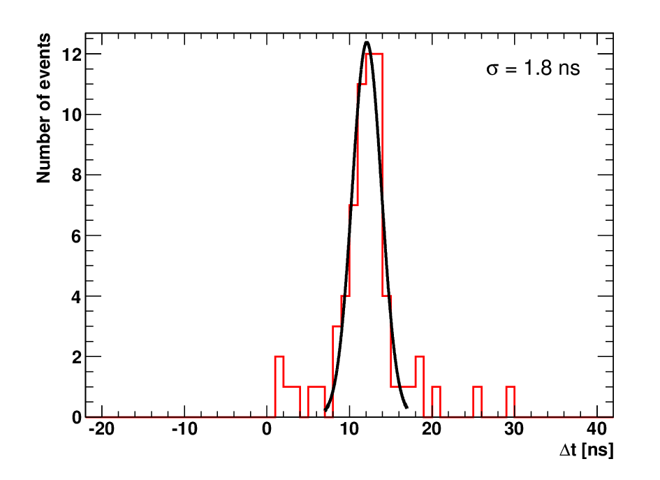
Digitised signals from the ADC are used to understand the performance of the system. It entirely meets the expectations as could be proved already in the first runs of LHC in 2008. The plots in Figure 3 show the signal-to-noise ratio of the detectors11 1 Channel 1 had a faulty cable in 2008. Meanwhile, this has been replaced, and Channel 1 delivers data as well. and a time resolution measurement [6]. The latter was taken while only one beam was circulating and shows the time difference between signals from sensors at opposite detector planes and equal azimuthal positions. The mean value of corresponds perfectly to the time of flight of relativistic particles for , and a standard deviation of results in a time resolution of .

3 Performance and Prospects of BCM1F
3.1 Signal Spectra from the ADC
ADC data have been invaluable for the commissioning of the system. They facilitate maintenance and can deliver online information as well. The pulse height spectrum of signals taken in a run with colliding bunches is displayed in Figure 5 for ADC input channel 0. The trigger used for this measurement is an analogue sum of all BCM1F channels. Therefore, a fraction of the events contains the baseline in this channel, which accumulates to the pedestal peak at about zero pulse height. The maximum position of the signal peak is considered the pulse height for single relativistic particles (MIP correspondence)22 2 The energy of relativistic particles will usually be larger than the energy of minimum ionising particles (MIPs), thus their energy loss will be slightly larger than that of MIPs. This effect is ignored here.. The local minimum between those peaks is used to determine the optimal threshold to be set in the discriminator.
The third peak as well as the adjacent cut at the upper end of the spectrum result from a limitation of the front-end electronics. At a pulse height of about ten times the MIP amplitude, the output signal of the laser driver goes into saturation.
![[Uncaptioned image]](1012.3580v1/pulseHeightSpectrum.png)
![[Uncaptioned image]](1012.3580v1/bunchStructure_data_sim.png)
3.2 Timing Information from the TDC
The arrival times of hits in BCM1F are recorded with the TDC. Given the spacing of between potential bunch crossings, time can be converted into a bunch number within the LHC orbit. An example of the count rate as a function of the bunch number is displayed in Figure 5. The first three peaks, corresponding to colliding bunches, exhibit very high count rates and long tails up to the range. Both effects are caused by collision products. The peaks around bunch number 1000 and 2000, respectively, represent the three non-colliding bunches of each beam. No tails are observed here.
A simulation has been performed [7] using FLUKA [8] to understand the reasons for the long tails of colliding bunches.33 3 The simulation is normalised to the data and does not include non-colliding bunches. The results agree well with the data, as can be seen in Figure 5, and confirm that, in addition to collision products and beam halo, also delayed signals from electrons, photons, and neutrons contribute to the count rates.
3.3 Online Analysis with Scalers
The output signals of the discriminator are also fed into scalers and a freely programmable logic unit, see Figure 2. The unit’s FPGA is programmed as a look-up table (LUT) to match pairs of BCM1F modules opposing with respect to the IP. Coincidences of signals in such back-to-back modules are assumed to be caused by elastic scattering in the collisions. Corresponding logical coincidence signals are counted by the scalers as well. In Figure 6, the overall coincidence rate and the luminosity measured by the hadronic forward calorimeter (HF) are plotted against time. The HF result (blue line) has been scaled to the BCM1F coincidence rate (green line), which has been fit (black line) in order to compare the slopes. In addition, the scaled count rate of BCM1F on the side is shown (red line). We observe a reasonable agreement between the three lines, demonstrating the potential of BCM1F to be used as a fast luminosity monitor.

References
- [1] The CMS Collaboration, The CMS experiment at the CERN LHC, \jinst32008S08004.
- [2] Alan J. Bell on behalf of the BRM group, Beam & Radiation Monitoring for CMS, 2008 IEEE Nuclear Science Symposium Conference Record, pp. 2322–2325.
- [3] A. Macpherson, Beam Conditions and Radiation Monitoring at the LHC Experiments, 2006 Proceedings LHC Project Workshop, Chamonix XV, p. 198.
- [4] R. Hall-Wilton, W. Lange, A. Macpherson, V. Ryjov, and R.L. Stone, Fast beam conditions monitor (BCM1F) for CMS, 2008 IEEE Nuclear Science Symposium Conference Record, pp. 3298–3301.
- [5] J. Kaplon and W. Dabrowski, Fast CMOS binary front end for silicon strip detectors at LHC experiments, 2005 IEEE Transactions on Nuclear Science 52(6), pp. 2713–2720.
- [6] A.J. Bell, E. Castro, R. Hall-Wilton, W. Lange, W. Lohmann, A. Macpherson, M. Ohlerich, N. Rodriguez, V. Ryjov, R.S. Schmidt, and R.L. Stone, Fast beam conditions monitor BCM1F for the CMS experiment, 2010 Nuclear Instruments and Methods in Physics Research A614, pp. 433–438. arXiv:0911.2480
- [7]
Steffen Müller on behalf of the CMS collaboration,
Impact of beam-induced backgrounds for the CMS Pixel and other inner radii detectors (Simulation and Data),
poster at the International Workshop on Semiconductor Pixel Detectors for Particles and Imaging, September, 6–10, 2010, proceedings to be published in Nuclear Instruments and Methods in Physics Research A, Special issue: PIXEL 2010.
Steffen Müller, Design, Commissioning and Performance of the CMS Beam Condition Monitor 2 and Simulation Studies of the Radiation Environment near CMS at LHC, 2010 Ph. D. Thesis in Preparation, CERN / KIT Karlsruhe. - [8] A. Fasso, A. Ferrari, J. Ranft, and P.R. Sala, FLUKA: a multi-particle transport code, 2005 CERN-2005-10, INFN/TC_05/11, SLAC-R-773.