Feedback control of noise in spin valves by the spin-transfer torque
Abstract
The miniaturisation of magnetic read heads and random access memory elements makes them vulnerable to thermal fluctuations. We demonstrate how current-induced spin-transfer torques can be used to suppress the effects of thermal fluctuations. This enhances the fidelity of perpendicular magnetic spin valves. The simplest realization is a dc current to stabilize the free magnetic layers. The power can be significantly reduced without losing fidelity by simple control schemes, in which the stabilizing current-induced spin-transfer torque is controlled by the instantaneous resistance.
pacs
72.25.-b,76.50.+g,75.70.Cn,72.80.Ga,75.60.JkMagnetic spin valves with metal or insulator spacers are used for hard disk read heads as well as for magnetic random access memory elements. The physical principle of operation is the giant magnetoresistance (GMR) or tunnel magnetoresistance (TMR), which vary with the relative magnetization between a layer with fixed magnetization (e.g. by exchange biasing) and a free layer with a magnetization that is allowed to (re)orient the magnetization direction. Further miniaturization is thwarted by the increased thermal fluctuations associated with smaller magnets, however, because the magnetic anisotropy energies scale with the total magnetic moment [1]. GMR read heads in the form of nanometer-scale pillars are currently considered as possible replacements for TMR read heads [2]. Their higher sensitivity comes at the cost of noise which is enhanced by the spin-transfer-torque-induced coupling of electronic and magnetic fluctuations [3, 4]. Here we demonstrate that the spin-transfer torque can also be used to suppress the noise in spin valves. The necessary power to achieve a given fidelity can significantly be reduced by feedback control of the electric current-induced torque by the instantaneous resistance.
An electric current passed through a spin valve interacts with the magnetic order parameter when the magnetizations are non-collinear. This is caused by the spin current component polarized normal to the magnetization of the free layer, which is absorbed at the interface. The loss of angular momentum in the spin current is transferred to the magnetization as a spin-transfer torque, [5, 6, 7, 8, 9, 10] which effectively leads to magnetic damping or anti-damping of the magnetization dynamics, depending on the current direction. Low frequency noise can be suppressed by increasing the magnetic anisotropy of the free magnetic layer at the cost of reduced sensitivity. Covington [3] proposes to reduce noise by applying a spin-transfer torque which opposes the intrinsic damping so that the effective damping is reduced. According to the fluctuation-dissipation theorem (FDT) the random field that perturbs the magnetization at thermal equilibrium is indeed proportional to the Gilbert damping constant (see Eq. (3) below). A reduced damping therefore reduces noise. However, in the presence of a spin-transfer torque driving force the FDT does not hold and a reduced damping does not improve read-head performance. In this Letter we prove that the opposite is true: we have to increase the damping in order to suppress the noise. Applying a dc current of the right direction we are able to increase the fidelity of the read head compared to the zero current situation. The draw back of this approach is the additional power that has to be invested for a given noise suppression. In search of a more energy-conserving method we propose to apply a time-dependent current that is controlled by the instantaneous magnetization configuration as measured by the GMR/TMR. We implement here two physically transparent feedback mechanisms, noting that performance could even be improved by making full use of sophisticated control theory.

Our model corresponds to a realistic [11, 12] nanopillar (FMNMFM) spin-valve as sketched in Fig. 1, consisting of a thick ferromagnet (FM) permalloy (Py) layer with fixed magnetization direction and a thin Py layer separated by a non-magnetic (Cu) layer. The pillar has an elliptical cross-section, which defines the easy axis of the free layer to be along . A charge current flowing from the thick layer to the thin layer in the perpendicular direction () is defined to be positive. The device is stable for a dc current up to [11]. The allowed peak value for a pulsed current is higher [13].
We assume a spatially uniform magnetization of the free FM layer (‘macrospin’ approximation). The temporal evolution of the magnetization vector of the free FM in presence of random field and a Slonczewski spin-transfer torque model can be described by the Landau-Lifshitz-Gilbert equation:
| (1) | |||||
The effective field / depends on the free energy density
| (2) |
where is the unit vector along the easy-axis. is the uniaxial anisotropic field and () [11] is the demagnetization field (last term in the free energy Eq. (2)) with demagnetization factors , , [14] and is the saturation magnetization. A weak ( [11]) external field is chosen to ensure no switching due to an applied in-plane field. The damping torque in Eq. (1) is proportional to the Gilbert constant . The next entry on the r.h.s. of Eq. (1) is a stochastic term. The stochastic field has zero mean and white noise correlation [15].
| (3) |
where is the thermal energy, is the gyromagnetic ratio and the volume of the free ferromagnet, and denotes statistical averaging. The last term on the r.h.s. of Eq.(1) is the spin-transfer torque parameterized by which has the dimension of magnetic field and it is proportional to applied current as where is the spin-polarisation.
We solve the Landau-Lifshitz-Gilbert equation numerically in the presence of stochastic torques at room temperature by the Heun method [16]. We use discretized time interval . We start from the initial state and study the temporal evolution of . We calculate the fidelity life time, which is defined as the average time it takes until the magnetization deviates from its initial equilibrium value beyond a cutoff (arbitrary choice). The typical value of fidelity life time in absence of applied current is as obtained from our calculations. We average over realizations.
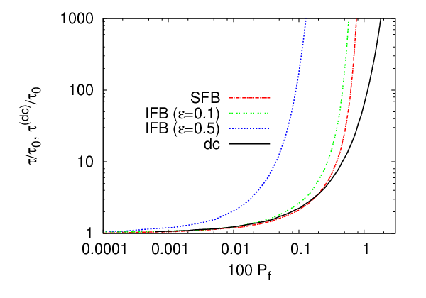
Let us first study the dynamics in the presence of a dc current and compute the fidelity time enhancement and the average dimensionless power consumption factor (the solid curve in Fig. 2). The dimensionless fidelity increases exponentially with the square of . Thus fidelity increases with magnitude of applied current (hence torque). As a test of our method we repeated the simulations of current induced magnetization reversal of Ref. [17] and found good agreement.
We propose two control methods to reduce power consumption, assuming that we can monitor the instantaneous magnetization in real time by the electrical resistance. First, we let the magnetization evolve from its initial equilibrium configuration in the absence of a spin-torque and apply a current pulse with constant magnitude when drops below a chosen lower bound (). We switch off the current pulse once reaches a chosen upper bound . We refer to this method as the simple feedback scheme (SFB). We compute the dimensionless fidelity life time and the dimensionless average power consumption factor , where is the total duration over which the spin-torque is in action. The result is shown as the dash-dotted line in Fig. 2. The fidelity life time as a function of invested power is very similar to the dc case. In the large power regime which also refers to large current regime, the SFB leads to significant power savings, however. A fidelity increased by a factor compared to the zero-torque situation can be gained by investing times less power as compared to the dc torque method. Here our approach is to apply a larger torque for shorter duration as large current ensures enhancement in fidelity and small duration makes the scheme power-saving one. Note that in our numerical simulation the magnitude of current pulses would be such that the magnetization switches slowly in the time-scale of , the chosen time-step. In the small regime, the smaller enhancement in fidelity (compare the dash-dotted curve with the solid one in Fig. 2) than dc case is due to the initial delay, set by on . With increasing torque, the initial delay becomes insignificant.
At this stage we devise an improved control of the current pulses to save much energy. This case will be called as improved feedback method (IFB). As in the ‘SFB’ case, we allow the magnetization to evolve from its initial state without applying a current. When drops below we turn on a pulsed current corresponding to a torque, which now is a function of . We have chosen , where corresponds to the initial value of the current pulse when it is turned on. and are two chosen cut-off values for as described above. Note that in the SFB case magnitude of the pulse current is whenever it is in action but in the present case increases monotonically when drops from and then decreases with increasing from in presence of spin-torque. Thus to estimate invested power we accumulate the power consumption factor at each time step i.e. . Since in the simulation we are using a finite time step, in practice, we do not reach the maximal current limit as . As soon as reaches we turn off the current again as in the SFB case. We carry out simulations for two values of the exponent in Fig. 2. For small , there is only a slight improvement (the double dashed curve in Fig. 2) in the result as compared to the SFB case. For an intermediate value , a significant improvement (the dashed curve in Fig. 2) is visible. A fidelity enhancement by a factor costs roughly times less power than in the dc limit. Larger requires a smaller size of time-step to get reliable convergence in the numerical integration.
We now estimate the typical power consumption of our feedback loop in a practical situation. The average power consumption is with and are system specific constant terms. For our system . For a resistivity [18] of thick Py at room temperature or resistance the constant . We consider the data from Fig. 2 for the fidelity time . For the ‘dc’ case, the enhancement is achieved by investing or average power . The same order of enhancement in fidelity is obtained by consuming or in SFB scheme by applying a current of pulse of equivalent magnetic field . For a valve with a cross-section this requires a current of magnitude which corresponds to a current density . Clearly, at such current densities our approach will break down due to Joule heating. For the IFB scheme the same enhancement in fidelity is achieved by investing or when . This strong reduction in the invested power will alleviate the aforementioned heating problem in SFB case. The efficiency (fidelity) of the operation depends on the different system parameters (spin-torque , external field, anisotropy and demagnetization field etc.), but also on the chosen cut-off value and the boundary values and . The qualitative message appears to be valid for all sensible parameter sets, however.
In conclusion, we propose to suppress noise in metallic magnetic spin valves making use of the current-induced spin transfer torque. With moderate power consumption it is possible to increase the fidelity of the device, especially when a feedback loop is implemented which controls the spin-transfer torque depending on the instantaneous magnetization configuration. The latter can be measured by the electric resistance. The correcting current pulses should have sharp rise and decay times which can be generated by state-of-the-art electronics [19]. Our method can be easily adopted to magnetic tunneling junctions. The method can be used to suppress noise in read heads and increase reliability of memory elements.
Acknowledgements.
This work was supported by the European Union via DYNAMAX and MACALO. SB acknowledges hospitality of TU Delft.References
- [1] Neil Smith and Patrick Arnett, Appl. Phys. Lett. 78, 1448 (2001).
- [2] S. Maat, N. Smith, M. J. Carey, and J. R. Childress, Appl. Phys. Lett. 93, 103506 (2008).
- [3] Mark Covington, United States Patent, US 7,042,685 B2(2006).
- [4] J. Foros, A. Brataas, Y. Tserkovnyak, and G. E. W. Bauer, Phys. Rev. Lett. 95, 016601 (2005).
- [5] J. C. Slonczewski, J. Magn. Magn. Mater. 159, L1 (1996).
- [6] L. Berger, Phys. Rev. B 54, 9353 (1996).
- [7] D. C. Ralph and M. D. Stiles, J. Magn. Magn. Mater. 247, 1190 (2007).
- [8] A. Brataas, Yu. V. Nazarov, and G. E. W. Bauer, Phys. Rev. Lett. 84, 2481 (2000).
- [9] A. Brataas, Yu. V. Nazarov, and G. E. W. Bauer, Eur. Phys. J. B 22, 99 (2001).
- [10] J. Z. Sun, Phys. Rev. B 62, 570 (2000).
- [11] S. I. Kiselev, J. C. Sankey, I. N. Krivorotov, N. C. Emley, A. G. F. Garcia, R. A. Buhrman, and D. C. Ralph, Phys. Rev. B 72, 064430 (2005).
- [12] S. Urazhdin, N. O. Birge, W. P. Pratt, Jr., and J. Bass, Phys. Rev. Lett. 91, 146803 (2003).
- [13] T. Devolder, J. Hayakawa, K. Ito, H. Takahashi, S. Ikeda, J. A. Katine, M. J. Carey, P. Crozat, J. V. Kim, and C. Chappert, Journal of Appl. Phys. 103, 07A723 (2008).
- [14] J. A. Osoborn, Phys. Rev. 67, 351 (1945).
- [15] William Fuller Brown, Jr., Phys. Rev. 130, 1677 (1963).
- [16] J. L. Garcia-Palacios and F. J. Lazaro, Phys. Rev. B 58, 14937 (1998).
- [17] N. C. Emley, I. N. Krivorotov, O. Ozatay, A. G. F. Garcia, J.C. Sankey, D. C. Ralph, and R. A. Buhrman, Phys. Rev. Lett. 96, 247204 (2006).
- [18] G. Counil, T. Devolder, J.-V. Kim, P. Crozat1, C. Chappert, S. Zoll, and R. Fournel, IEEE Trans. Mag. 42, 3323 (2006).
- [19] O. J. Lee, V. S. Pribiag, P. M. Braganca, P. G. Gowtham, D. C. Ralph, R. A. Buhrman, and F. J. Lazaro, Appl. Phys. Lett. 95, 012506 (2009).