Nonlinear behavior of memristive devices and their impact on learning algorithms like STDP in memristive neural networks
Abstract
It is now widely accepted that memristive devices are perfect candidates for the emulation of biological synapses in neuromorphic systems. This is mainly because of the fact that like the strength of synapse, memristance of the memristive device can be tuned actively (e.g., by the application of voltage or current). In addition, it is also possible to fabricate very high density of memristive devices (comparable to the number of synapses in real biological system) through the nano-crossbar structures. However, in this paper we will show that there are some problems associated with memristive synapses (memristive devices which are playing the role of biological synapses). For example, we show that the variation rate of the memristance of memristive device depends completely on the current memristance of the device and therefore it can change significantly with time during the learning phase. This phenomenon can degrade the performance of learning methods like Spike Timing-Dependent Plasticity (STDP) and cause the corresponding neuromorphic systems to become unstable. Finally, at the end of this paper, we illustrate that using two serially connected memristive devices with different polarities as a synapse can somewhat fix the aforementioned problem.
1 introduction
Publication of a paper [1] in Nature by HP labs in May 1, 2008, which announced the first experimental realization of the memristive device whose existence was predicted in 1971 by Leon Chua [2] has caused an extraordinary increased interest in this passive circuit element. A memristive device is a device that, like a resistor, opposes the passage of current. But memristive devices also have a memory. The memristance of a memristive device at any moment depends on the history of the applied voltage, so its behavior can be used to recall past voltages. One of the widely accepted application of memristive devices is in the hardware implementation of synapses in neuromorphic systems (for example see [3, 4, 5, 6]). Using memristive devices as synapses in neuromorphic systems can offer both high connectivity and high density (through the memristive crossbar structure) which are necessary for efficient computing. However, in this paper we will show that although memristive devices behave so similar to biological synapses, they have an unwanted property that may affect the efficiency of the hardware implementation of neuromorphic systems considerably.
The rest of this paper is organized as follows. In Section 2 we show that memristive devices have this property that their memristance change due to the applied voltage or current with a rate which is proportional to their initial memristances. Moreover, we show how this phenomenon can affect the working procedure of one of the well-known learning methods in neuromorphic systems i.e. STDP. The illustration of how this aforementioned problem can cause neuromorphic systems to become unstable is presented in Section 3. Our proposed method to relax this problem is explained in Section 4, and finally, Section 5 concludes the paper.
2 Some Problems behind using memristive devices as synapse
As stated before, now it is well-known that the main contribution of memristive devices in neuromorphic systems comes from their ability to emulate the role of synapses in biological systems. This is because of the fact that the memristance or memductance of memristive devices can be tuned by the application of an appropriate voltage or current signal to them. Therefore, it can be said that memristance or memductance of memristive devices simply acts similar to synaptic weights in biological systems. Figure 1 shows a typical but not necessarily efficient neuromorphic system which is constructed based on these nanoscale passive elements and used in some recent studies [7]. In this figure, memristive devices are fabricated between two perpendicular wires in every crosspoints of the crossbar and each rows of the crossbar is connected to the virtually grounded input terminal of an operational amplifier. Each of these operational amplifiers plays the role of neurons in biological systems and their efficient hardware implementation is beyond the scope of this paper. Note that in this figure, memristive devices are depicted explicitly to have better visibility. Meanwhile, usage of the virtually grounded operational amplifiers in this configuration is necessary to have a weighted sum of the applied input voltages at their outputs. Since the combination of each of these opamps with those memristive devices located on the corresponding row of the crossbar creates a simple opamp-based summing circuit, output of the ith neuron can be written as:
| (1) |
or
| (2) |

where and are respectively the current memristance and memductance of the memristive device at the intersecting point of the ith horizontal and the jth vertical wire of the crossbar, is a constant feedback resistor of opamps, and are the number of rows and columns of the crossbar respectively and is the voltage signal applied as an input to the jth column of the crossbar. Note that although these two equations are the same (since ), but the first one should be used for the charge-controlled memristive devices while the second one is appropriate for the flux-controlled memrstive devices [2].
Here, we can see the first problem associated with this kind of structures: synaptic weights (i.e. ) relate inversely and nonlinearly to the memristance of memristive devices. As a result, those learning algorithms which are working by tuning of the memristance of memristive devices may require an extra step to convert synaptic weights to the memristance of memristive devices and vice versa or at least they should consider this note.
As another disadvantage, all synaptic weights ( or ) in the structure of Fig. 1 are always negative (even they cannot become zero although they may be sufficiently small). Adding auxiliary circuits to the structure of Fig. 1 (for example by considering two or more memristive devices to represent one synaptic weight) to compensate this drawback will increase the complexity of the associated learning method. One simple but effective solution to overcome this problem for this kind of networks is to use those learning rules that generate either positive or negative synaptic weights. For example, in our recently proposed memristive neuro-fuzzy computing system [8], we have trained a similar memristive network with a Hebbian-like learning rule with only non-negative synaptic weights.
However, probably the most important disadvantage of using memristive nanodevices in any kind of neuromorphic systems independent from their structural configuration relates to antithetical behavior of these passive elements during the learning process. This antithetical behavior is the result of memristive device’s inability to act equally in the following two different situations which occur frequently during the learning process: (i) memristance increasing and (ii) memristance decreasing periods of memristive devices. By precisely investigating the working procedure of memristive devices while subjected to external voltages we can observe that the response of these devices completely depends on the polarity of the applied voltages and their initial conditions. To clarify this issue better, here we briefly review the behavioral characteristics of some of the well-known memristive devices fabricated recently.
Let’s begin from the most primary fabricated memristive nanodevice, i.e. HP device. In this device, a thin semiconductor film of thickness is sandwiched between two metal contacts and the boundary between doped (with length ) and undoped (with length ) regions can be moved by the application of external voltage bias . By considering a linear ionic drift in a uniform field (ignoring boundary effects) with average ion mobility , memristance of this memristive device can be simply written as [1]:
| (3) |
| (4) |
where and are the minimum and the maximum memristances that the memristive device can take and is the corresponding current passing through the device.
By solving equation (4) with respect to we will have:
| (5) | |||||
Now, based on equations (5) and (3) we can simply draw the memristance of the HP device, i.e. , versus any applied voltage for any initial condition (i.e. or equally ). For example, Fig. 2 shows how the memristance of this memristive device varies (from to and vice versa) when the input is a successive positive voltage pulses followed by a successive negative voltage pulses with the amplitude of 2 volts each for a duration of 120 seconds. As this figure indicates, variation rate (slop) of the memristance of this memristive device is proportional to the polarity of the applied voltage and the initial memristance of the device. This means that the memristance of the memristive device will change with different amounts in different conditions even if the applied signal be the same. In learning process, this will be translated to having different and distinct time-varying learning rate for each synaptic weight. For example, in Fig. 2, when the applied voltage is positive, the learning rate is increasing with time while by changing the polarity of the applied voltage, learning rate begins to decrease with time. As a result, every memristive device used in any neuromorphic system will have its own memristance-based learning rate. This may cause the system to become unstable since the learning rate of some synaptic weights may be very small (for example point A on Fig. 2) while at the same time other’s learning rate may be very high (for example point B on Fig. 2). In the next section, we will discuss a bit more about this fact (i.e. possibility of the divergence of the memristive neuromorphic system).

This phenomenon (explained above) can be seen even in more realistic memristive devices as well. For example, in [9], a nonlinear memristive model of bipolar switching is presented which is derived from the experimental results of a dynamical testing protocol applied to a set of Pt--Pt crosspoint devices. Here we have presented these experimental results in Fig. 3 for convenience (note that in these figures, is the length of the undoped region of the device (unlike the case we had in HP device which was the length of the doped region) and therefore higher will correspond to higher memristance). Figure 3 shows how the state variable and consequently the memristance of the device varies during six off-switching tests with external voltage ranging from 3.0 to 5.5V. By changing the polarity of the applied voltage we will have the on-switching case which is shown in Fig. 3. As stated in [9] as well, it is clear from these figures that the switching speed strongly depends on the current state of and the polarity of the applied voltage. For example, Fig. 3 shows that memristance of the device changes rapidly at first and its rate begins to decrease by time. In Fig. 3, we see a completely different case: when the input voltage is negative, memristance of the device changes more rapidly compared with the case in which input voltage is positive. As stated before, this means that based on the current state and condition, applied identical positive or negative pulses may have completely different effect on the memristance of the memristive device. In learning algorithms like Spike Timing-Dependent Plasticity (STDP), this may correspond to having different step size for each synaptic weight which its characteristics depend not only on the current memristance of the device but also to the polarity of the applied voltage.


To clarify the effect of this phenomenon on the working procedure of memristive computing systems, consider the neuromorphic structure shown in Fig. 4. In this figure, two neurons are connected to each other through the memristive synapse. It is well-known that one of the main defining feature of connections between neurons in biological systems is that they become stronger when neurons fire together; hence the phrase “neurons fire together, wire together”, an event otherwise known as Hebbian learning [10]. Various experiments have shown that this effect is most pronounced early in the learning process when the increase in connection strength is greatest while later learning merely reinforces the links between neurons. However, that is somewhat at odds with the actual behavior of memristive devices used as synapse. For example, consider the memristive device connecting two neurons in Fig. 4. Memristance of this passive device decreases when a voltage is applied to it which increases its current which in return causes the memristance to drop further in a kind of positive feedback effect. Note that although a lower memristance allows more current to flow so this certainly increase the strength of the connection as expected but because of the mentioned positive feedback, later signals will have a bigger effect on the connection than earlier ones. This is the opposite way round to the way real neurons connect, where earlier signals have the strongest effect. In other words, early experiments should have the most impact on learning and not the later ones while this is not the case in structures like the one shown in Fig. 4. Here it is worth to mention that this problem cannot be solved by initializing the memristance of memristive devices representing synaptic weights to rather small values at the beginning of training phase as suggested in [11]. This is because of the fact that in learning algorithms like STDP (as they used), synaptic weights may change in both directions (up and down) at any time and therefore initialization of the memristance of memristive devices to rather small value is not effective and do not solve the problem for subsequent steps of the learning process. Note that this solution may be efficient only for those learning methods in which synaptic weights vary only in one direction (for example see [12, 8]).

This natural behavior of memristive devices and its associated problem for neuromorphic systems as explained above can be seen in some other reported memristive systems as well. For example, authors in [13] have presented a new Pd//W flux-controlled memristive devices. Although they have argued that the memductance change in each voltage cycle for their memristive device was roughly constant but their reported experimental results show something else. For example, see Fig. 5 for the resistance switching characteristics of their memristive device when subjected to five consecutive negative voltage sweeps. From this figure of the paper, it is evident that the voltage sweep no. 6 has changed the memductance of the device more than what voltage sweep no. 10 or no. 9 has done. In addition, those results (for example see Fig. 6(a) of the paper) which are obtained by using their own reported final model for their memristive device (although the model has this problem that by setting the applied voltage into zero, memductance of the device will continue changing) have also the same problem.

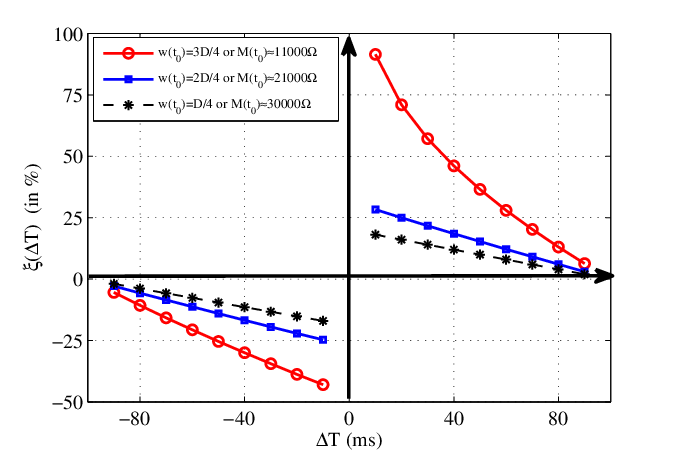
Finally, let’s investigate the effect of this phenomenon on one of the most famous learning algorithms of neuromorphic systems i.e. STDP. The STDP algorithm is usually recognized by its update function (changing amount of synaptic weight versus relative timing of the spikes of neurons) [14, 15]. Dependency of the memristive device’s response on its initial memristance or memductance results in having completely different STDP update function for each initial condition. For example, in Fig. 6 we have plotted the update functions for one memristive synapse (in this case HP device) for three different initial conditions: , and . It can be inferred from this figure that during the learning phase of memristive neuromorphic systems, each memristive device because of its different memristance or memductance will have a completely different update function .
3 The neuromorphic system realized through memristive devices may not converge during learning phase
In this section we will show why the memristive neuromorphic system may become unstable during the learning phase or why it may not converge to global extremum. For this purpose, assume that we have a simple neuromorphic system with only two synaptic weights realized through memristive devices. Moreover, let’s assume that this system has a cost function such as a typical one depicted in Fig. 7 which should be minimized with respect to synaptic weights and during the learning phase. As can be seen in Fig. 7, this typical cost function has one global and two local minima. Now if we start from point C on the surface of the cost function of Fig. 7, then the application of an optimization method like steepest descent will cause the weights vector to move along vector toward the global minimum. This vector can be decomposed into two vectors and which means that by application of the optimization method, synaptic weights and should move along vectors and respectively. However, if the learning rate of the synaptic weight , i.e. , be much higher than the learning rate of the synaptic weight , i.e. , the weight vector will move along vector toward local minimum rather than global minimum. In this case, the neuromorphic system under consideration will converge to a wrong state. This problem shows itself better when we note that these learning rates can differ significantly based on the current memristance of those synaptic weights which are realized through memristive devices. To verify this claim, we conducted a simple experiment. In this experiment, we applied a positive voltage pulse with fixed duration to a simple memristive device (using HP model) with different initial memristances and measured the amount of memristance change in percents due to the applied voltage. The result of this experiment is presented in Fig. 7. This figure shows that if we implement a neuromorphic system by using this memristive device, then those synaptic weights which their corresponding memristive devices have low memristances will have a learning rate of about times higher than the learning rate of those synaptic weights which their corresponding memristive devices have high memristances.


Finally, by considering Fig. 7, it should be noted that this aforementioned problem about the possibility of the divergence of the neuromorphic system can be relaxed by decreasing the overall learning rate of the system for example by decreasing the duration of the voltage pulse used for changing the memristance of memristive devices. However, this solution will definitely decrease the learning speed of the system.
4 One simple solution to overcome some of these mentioned problems
To overcomes some of these problems, we propose to use the combinational element shown in Fig. 8 as a synapse. In this figure, two memristive devices with different polarities are connected in series. In fact, memristive device plays the role of synaptic weight and it will be used during normal working of the system. On the other hand, memristive device is added only to remove the aforementioned problem during learning phase. Figure 8 is a typical circuit which shows how these combinational elements can be used to create a neuromorphic computing system. In this circuit, devices and are memristive synaptic weights and and are the applied input voltages (either external voltages from sensory neurons or internal voltages from other neurons in the system). During the normal working phase of this neuromorphic system, switches and will be close while switch is open (note that one signal will be sufficient to control all of these switches). In this case, the structure of Fig. 8 reduces to the ordinary memristive neuromorphic structures such as the one depicted in Fig. 1 and the output of the system will be the weighted sum of input signals. However, during the learning phase, switches and become open while switch is closed. In this configuration, a voltage difference between spikes of presynaptic and postsynaptic neurons due to their timing mismatch will drop this time across two memristive devices instead of one compared with the structure of Fig. 1. Now, synaptic weights and see another memristive device with opposite polarity on their way which may affect their memristance variation rate during the learning phase.
Here, let’s see how adding these auxiliary memristive devices affects the updating process of memristive synaptic weights. For the purpose of simplicity, we use the model of HP’s memristive device (considering a linear ionic drift in a uniform field and ignoring boundary effects) for the elements in Fig. 8. It follows from the Kirchoff’s laws that if two memristive devices and which are connected in series have opposite polarities, their total memristance can be written as [16]:
| (6) |
which can be rewritten as:
| (7) |
where:
- •
for is the effective memristance of the memristive device at time ;
- •
is the polarity of the memristive device which can be +1 and -1;
- •
;
- •
is the amount of charge that has passed through the devices;
- •
is the charge that is required to pass through the memristive device for the dopant boundary to move through distance where is the total length of the memristive device.
This equation shows that by connecting two memristive devices in series but with different polarities we can suppress the q-dependent component (second term in eq. (7)). In addition, it is clear that the overall behavior of these two memristive devices depends on the relationship between and or simply on . By properly adjusting we can choose how the memristance of the memristive device changes versus the applied voltage. Here it is worth to mention that two memristive devices connected in series acts completely the same as a single memristive device (their overall behavior is the same as the behavior of single memristive device). However, it should be noted that here we have two memristive devices during the learning phase but only one of them will be used in the computation phase. In the other words, changing rate of the memristance of the memristive device in Fig. 8 can be completely different from the changing rate of the overall memristance of two memristive devices which are connected in series.
Figure 8 shows how the memristance of the memristive device of Fig. 8 varies versus the applied voltage when . This simulation result is obtained by applying a successive positive voltage pulses followed by a successive negative voltage pulses (similar to what we had in Fig. 2) between input terminals 1 and 3 and then plotting the memristance of versus time. It can be inferred from this figure that when two serially connected memristive devices have similar s (i.e. ), memristance of will change almost linearly with time and therefore early and later applied pulses will have the same effect on the memristance of the device. In addition, it is interesting to note that as can be seen in Fig. 8 as well, initial memristance of the memristive device determines the variation rate of the memristance of . It means that during the learning phase of those neuromorphic structures which are using this kind of synapse, we can change the learning rate of the system simply by modifying memristance of . For example, to slow down the learning process we can simply increase the memristance of which can be done even when the system is running. In Fig. 8, we have a completely different case. This figure shows how the memristance of varies when (in this figure ). It can be seen that when is much larger than , memristance of varies with different rates depending on its memristance value. Again, by changing the initial memristance of , we can modify the learning rate of the system. Finally, Fig. 8 shows the case of (in this figure ). Since the memristance of is negligible compared with the memristance of , memristive device and consequently its initial memristance will have almost no effect on the variation rate of the memristance of and therefore we see the same result as we had in Fig. 2.


Another advantage that the structure of Fig. 8 offers is its ability to fix the problem of having different STDP update function for each initial condition (memristance value) as we explained before (see Fig. 6). This can be achieved by satisfying two distinct conditions simultaneously: (i) using memristive devices with the same in the entire system (therefore having Fig. 8 for the variation rate of all synaptic weights) and (ii) setting the initial memristances of all pairs of memristive devices which are connected in series in a way that the sum of their initial memristances be equal to some predetermined fixed value. Note that this should be done only once in the initialization phase. Since the two memristive devices connected in series are similar but have different polarities, the sum of their memristances at any time during the learning phase will remain almost constant and equal to the predetermined value. Therefore, during the initialization phase, it is only required to set the memristance of each of the auxiliary memristive device with the predetermined value minus the initial memristance of its corresponding memristive device acting as a synaptic weight. In this case, since every two connected memristive devices are the same, as showed earlier in Fig. 8, variation rate of the memristance of memristive devices will be constant. In addition, since the total memristance of the two serially connected memristive devices is always constant, the current passing through the devices will always be the same and therefore the initial memristance of the memristive device acting as a synapse will not affect the STDP update function. Figure 9 shows the STDP update function for this special configuration for three different initial conditions. It can be seen from this figure that unlike Fig. 6 which was obtained by using only one memristive device as synapse, the STDP update function is almost the same for all synaptic weights even with different initial memristances.

Finally, it is worth mentioning that although here we used the simple HP model for our memristive devices, most of the problems and solutions presented in this paper will be valid for other type of memristive devices as well. For example, consider the boundary effect. This effect will only show itself when the memristance of the memristive device is near to its maximum or minimum value (i.e. or respectively) and in other cases it will be negligible.
5 conclusion
In this paper we showed that using a memristive device as a synapse has some drawbacks. For example, we demonstrated that during the learning process, variation rate of synaptic weights (memristance of memristive devices) varies significantly from one memristive device to another one based on the memristance of the device. This results to have one distinct STDP update function per each individual synaptic weight which may cause the neuromorphic system using this learning method to diverge. To solve this problem, we proposed to use two serially connected memristive devices with different polarities as a synapses. Simulation results show that by proper adjustment of the characteristics of these two memristive devices, it is possible to overcome this aforementioned problem.
References
- (1) D.B. Strukov, G.S. Snider, D.R. Stewart and R.S. Williams, “The missing memristor found,” Nature, 2008, vol. 453, pp. 80–83, 1 May 2008.
- (2) L.O. Chua, “Memristor - the missing circuit element,” IEEE Trans. on Circuit Theory, vol. CT-18, no. 5, pp. 507–519, 1971.
- (3) S. H. Jo, T. Chang, I. Ebong, B. B. Bhadviya, P. Mazumder, and W. Lu, “Nanoscale Memristor Device as Synapse in Neuromorphic Systems,” Nano Letter, 2010, 10(4), pp. 1297–1301.
- (4) K.D. Cantley, A. Subramaniam, H.J. Stiegler, R.A. Chapman, E.M. Vogel, “Hebbian Learning in Spiking Neural Networks With Nanocrystalline Silicon TFTs and Memristive Synapses,” IEEE Transactions on Nanotechnology, vol. 10, no. 5, pp. 1066 - 1073, September 2011.
- (5) Y. V. Pershin, M. Di Ventra, “Neuromorphic, Digital, and Quantum Computation With Memory Circuit Elements,” Proceedings of the IEEE, DOI: 10.1109/JPROC.2011.2166369, October 2011.
- (6) G. Snider, R. Amerson, D. Carter, H. Abdalla, M.S. Qureshi, J. Leveille, M. Versace, H. Ames, S. Patrick, B. Chandler, A. Gorchetchnikov, E. Mingolla, “From Synapses to Circuitry: Using Memristive Memory to Explore the Electronic Brain,” IEEE Computer, vol. 44, no. 2, pp. 21–28, February 2011.
- (7) G. Snider, “Spike-Timing-Dependent Learning in Memristive Nanodevices,” IEEE International Symposium on Nanoscale Architectures, pp. 85–92, June 2008.
- (8) F. Merrikh-Bayat, and S. Bagheri Shouraki, “Memristive Neuro-Fuzzy System,” Submitted to IEEE Trans. on Systems, Man, and Cybernetics, Part:B.
- (9) M. D. Pickett, D. B. Strukov, J. L. Borghetti, J. J. Yang, G. S. Snider, D. R. Stewart, and R. S. Williams, “Switching Dynamics in Titanium Dioxide Memristive Devices,” Journal of Applied Physics, 106, 074508, 2009.
- (10) D. O. Hebb, “The Organization of Behavior,” New York, Wilew, 1949.
- (11) C. Zamarreño-Ramos, L. Camuñas-Mesa, J. A. Pérez-Carrasco, T. Masquelier, T. Serrano-Gotarredona, and B. Linares-Barranco, “On Spike-Timing-Dependent-Plasticity, Memristive Devices, and Building a Self-Learning Visual Cortex,” Frontiers in Neuromorphic Engineering, Front. Neurosci. 5:26, 2011. doi: 10.3389/fnins.2011.00026, 17 March 2011.
- (12) F. Merrikh-Bayat, S. Bagheri Shouraki, and A. rohani, “Memristor Crossbar-Based Hardware Implementation of the IDS Method,” IEEE Trans. on Fuzzy Systems, Vol. 19, No. 6, pp. 1083–1096, December 2011.
- (13) T. Chang, S.H. Jo, K.H. Kim, P. Sheridan, S. Gaba, W. Lu, “Synaptic Behaviors and Modeling of a Metal Oxide Memristive Device,” Appl Phys A (2011) 102: 857863. DOI 10.1007/s00339-011-6296-1.
- (14) G. Bi and M. Poo, “Synaptic Modifications in Cultured Hippocampal Neurons: Dependence on Spike Timing, Synaptic Strength, and Postsynaptic Cell Type,” Journal of Neuroscience, vol. 18, no. 24, pp. 10464–10472, 1998.
- (15) G. Bi and M. Poo, “Synaptic Modification by Correlated Activity: Hebbs Postulate Revisited,” Annual Review of Neuroscience, vol. 24, no. 1, pp. 139–166, 2001.
- (16) Y. N. Joglekar, S. J. Wolf, “The Elusive Memristor: Properties of Basic Electrical Circuits,” European Journal of Physics, Vol. 30, no. 4, pp. 661–675, 2009.