Magnetic domain walls displacement : automotion vs. spin-transfer torque
Abstract
The magnetization dynamics equation predicts that a domain wall that changes structure should undergo a displacement by itself - automotion - due to the relaxation of the linear momentum that is associated with the wall structure. We experimentally demonstrate this effect in soft nanostrips, transforming under spin transfer torque a metastable asymmetric transverse wall into a vortex wall. Displacements more than three times as large as under spin transfer torque only are measured for 1 ns pulses. The results are explained by analytical and numerical micromagnetics. Their relevance to domain wall motion under spin transfer torque is emphasized.
pacs
72.25.Ba, 75.60.Ch, 75.78.FgThe displacement of magnetic domain walls (DW) by spin transfer torque (STT [1]) is presently considered as a means of control in device applications [2]. It also raises fundamental questions about the description of electronic transport in magnetic media [3], fostering many experimental [4, 5, 6, 7] and theoretical [8, 9, 10] studies. The former can be divided into two groups, according to the duration of current application. With long (s) pulses, average wall velocities much lower than micromagnetic expectations [11] have been first observed [4, 12]. In this regime, sample heating limits the applicable current densities, and wall motion occurs under a strong influence of pinning [13]. For short ( ns) pulses however, higher apparent DW velocities have been reported [14, 6, 15], interpreted by an easier depinning due to an additional force on the DW during the pulse risetime [16]. The measurement of the DW velocity under STT is of importance because theoretical predictions relate the fundamental parameters of spin-polarized electron transport to the initial [17, 18] and steady-state [9, 11] DW velocities.
Under pulsed field, however, another type of DW motion has been documented, known as streaming or gyromagnetic [19], overshoot or automotion [20], depending on the field direction. The common ingredient to these situations is that certain changes of the wall structure lead to a wall displacement. This is ultimately related to the fact [21, 22] that a characteristics of the wall structure (equivalent to an angle of the wall magnetization) plays the role of a linear momentum conjugated, in Hamilton’s sense, to the wall position. Even if these earlier works considered Bloch walls, where the concept of a wall angle is intuitive, it was recently shown to apply to any type of wall [18]. As changes of the wall structure after a current pulse have been observed in some cases [5, 2, 23], it is important to experimentally evaluate the wall displacement purely due to this change. In particular, does automotion persist in presence of the unavoidable sample imperfections that pin the wall, and what is the signature of this phenomenon ? This is the object of the experiments described in this Letter. We apply high resolution magnetic force microscopy (MFM) to observe wall structure and position in permalloy nanostrips, before and after sharp current pulses of nanosecond duration. Automotion is demonstrated, with a large DW displacement in a direction related to the sense of the wall angle change, rather than to current polarity. The observations are interpreted, qualitatively and quantitatively, by micromagnetics.

Observations were performed in a MFM fitted with RF connection in order to apply short current pulses (rise and falltimes below 100 ps). Special care was taken for decreasing and controlling the magnetic perturbation due to the tip. First, the silicon tips were coated with a very thin Co70Cr30 4.5 nm layer with low coercivity, so that the tip reverses under the DW stray field. This means that the tip-sample interaction is always attractive, as testified by dark DW MFM contrasts. Second, two actions of the tip were sometimes observed, in which the DW was either snatched at tip approach, or dragged along with the tip. The snatch-up case, occuring for a tip nm away from the DW position (consistent with the 10 Oe DW propagation field measured for this sample), little affects the scatter of the measured DW displacements. In the cases of dragging (10% frequency), the displacement incurred was subtracted from the raw displacement.
Samples were prepared from a magnetically soft Pd(3.5)/Ni80Fe20(17.5)/Pd(3.5) layer (thicknesses in nanometers) patterned by e-beam lithography and lift-off into nanostrips nm wide and 12 m long. A Ti(3)/Au(100) coplanar waveguide connecting the sample was fabricated in a second step. Given the samples width and thickness, vortex walls (VW) are energetically stable [24]. Nevertheless, the DW initial state prepared by saturating the sample with a strong transverse field (1 kOe) is a metastable [25] asymmetric transverse wall (ATW, Fig. 1a,d). Once the created ATW is imaged, a current pulse, 1 ns long and in the range of amplitudes for STT (a few TA/m2), is applied. The transformed DW is then imaged, revealing its detailed structure and displacement. Samples have the shape of an ‘S’ so that two different walls are simultaneously nucleated.
Fig. 1 shows typical results, where the ATW transformed to the stable VW structure. In every case, a DW displacement was observed, either along the direction of electron flow (a-b) or in the opposite direction (d-e). The typical displacement, 1 m, would correspond to a 1 km/s effective velocity, a very large value considering the current density of 2.4 TA/m2 (equivalent to a 84 m/s spin drift velocity [11]). Moreover, displacement in both directions is observed, which is not consistent with STT. The direction of displacement is however not random. For example, the two ATW in Fig. 1, created by the same transverse field, have the same domain and wall magnetization directions, but opposite asymmetries. The asymmetry, seen as an inclination of the contrast along the nanostrip length, in either direction, appears randomly upon nucleation. We also remark that the polarities of the vortex cores in the final states are opposite (this polarity appears in the MFM images, as a continuity or an interruption of the contrast of the two wings of the VW, due to the superposition of DW and vortex core magnetic charges).
We study these phenomena with the Landau-Lifschitz-Gilbert equation for magnetization dynamics, augmented with the STT terms [9, 11]. The analytical analysis capturing the physics of the DW displacement upon transformation is first recalled. As the relaxation time of the vortex wall structure is much longer than the current pulse duration, the transformation essentially takes place without current. The dynamics of a DW structure in the absence of any external torque is termed automotion. For the geometry of a DW in a nanostrip, it has been shown that, whatever the wall type, the following equation then holds [18]:
| (1) |
where is the generalized wall magnetization angle, the (generalized) wall position, and the Thiele domain wall width. When the DW structure is planar and transforms by the motion of one vortex, the DW displacement obtained by time integration )under the assumption of a constant DW width) reads . Its sign is fixed by the vortex core polarity and by the path followed by the core (the change of its position across the width of the nanostrip). The three quantities , and are directly observed by MFM. For the last quantity, one should notice that the ATW structure has a position where a vortex is most easily injected, namely the half hedgehog vortex (1/2 HV, see Ref. [26]), indicated in Fig. 1. A proof of this injection path is obtained by comparing the inclination of the stripe in-between the two wings of the VW to the inclination of the ATW. As the initial is 0 or and the final , is . It is observed that the signs of all displacements observed under ATW to VW transformations are explained by this simple relation.

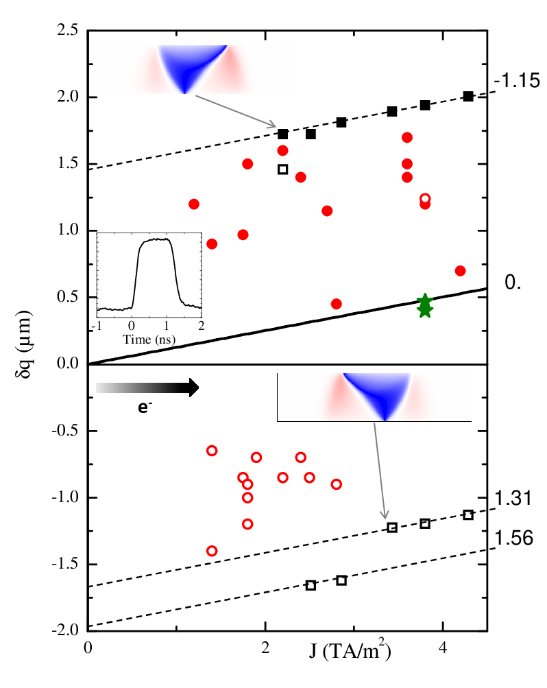
The magnitude of the displacements is now discussed. The measurements, on 8 different samples with slightly varying widths nm, for different current directions and ATW asymmetries, are gathered in Fig. 2. Both positive (along the electron flow) and negative DW displacements are observed, the sign correlating with the ATW asymmetry, except in one case. The displacements are very different from those expected for a pure STT effect (shown by the solid line). On the other hand, the calculated Thiele DW width being nm for a nm2 nanostrip [18], the analytical model predicts a displacement m for a damping . Numerical micromagnetic computations were also performed, using a homemade code [27] adapted to the infinite nanostrip geometry with a moving calculation box centered on the DW. Parameters were: current polarization , non-adiabatic STT coefficient , damping constant , and mesh size nm3. The Oersted field created by the current was included. These numerically computed displacements are reported in Fig. 2. The computed minimum current density for DW transformation is 2.3 TA/m2, a value above the experimental result, however obtained for a perfect nanostrip (it was even larger for lower , or when neglecting the Oersted field). The calculations also show the clear correlation of displacement sign with ATW asymmetry. Regarding magnitudes, one observes that the largest experimental DW displacements are close to calculations, using the effective value that has been recognized as appropriate for DW dynamics in NiFe [28, 29]. Smaller experimental displacements are ascribed to sample imperfections pinning the DW.
In addition, the calculations reveal that displacements increase with current density, with a slope similar to the STT contribution. However, the data form groups with different zero-current extrapolated displacements, only the largest reaching the analytical value. This shows that the ATW transformation is in fact complex. Indeed, calculations show that vortex cores sometimes reverse polarity, this mostly happening shortly after vortex injection, when the driving force towards the nanostrip center causes large vortex core velocities. In such cases, the contributions of all cores have to be added (with a minus sign for antivortices), leading to reduced and sometimes reversed displacements as well as to reduced values of (see Fig. 2).
Fig. 3 details the numerical results for the situation of Fig. 1. The ATWs with opposite asymmetries finally move in opposite directions, and magnetization snapshots show that vortices of opposite polarities finally appear, even if identical vortices are initially injected at the 1/2 HV positions [30]. Note that the displacements extend over 20 ns, which corresponds to the large relaxation time of the VW (7.5 ns according to Ref. [18]). In addition, the figure also shows the results for a VW: the angle increases during the pulse (less than for the ATW as the DW relaxation time is larger), and then goes back to zero so that no transformation occurs, the VW ultimately moving by 360 nm. Contrarily to automotion by transformation where the displacement is quantized (strictly if no vortex core switching occurs), this pure STT displacement depends on , and pulse length. An experimental comparison of the displacements under DW structure transformation and under pure STT is presented in Fig. 4. For the short pulse used here (1 ns), the displacement due to automotion by transformation clearly dominates. Note also that the value of the VW displacement is consistent with the value chosen for the simulations.

Thus, we have experimentally demonstrated that DW automotion during a structure transformation gives rise, in real samples, to measurable displacements. A signature of the effect is the direct relation with the change of generalized wall angle, as checked by high resolution MFM imaging. The situation chosen for this demonstration was that of a metastable ATW, frequently encountered in experiments, but the conclusions are general: a DW transformation, whatever its cause (field [31], current, etc) that modifies the generalized wall angle , leads to an intrinsic and large (for small damping) DW displacement. Note also that the same physical arguments should apply to samples with perpendicular magnetization. We thus propose that, once the damping constant relevant for DW dynamics is known, the magnitude of the displacement by automotion be taken as a measure of sample quality. When a DW transformation occurs, automotion dominates as soon as the duration of excitation is short compared to the relaxation time of the DW structure: the linear momentum bestowed to the DW when it starts transforming is very large as is far from equilibrium, and it is damped over the relaxation time. In particular, the resulting displacement is of a different nature, and much larger than that due to the pulse risetime effect [16], derived in the small approximation that forgets the possibility of a transformation: for the short pulses (compared to the relaxation time of the DW structure) applied here, the force due to the pulse risetime effect is a that causes no motion.
Automotion may impact the measurements of DW displacement under pulsed excitation (field, or spin-polarized current). This is especially true for experiments in which a new DW is created prior to the application of each pulse: if this DW is not in the stable state, a transformation with a large angle change will occur, resulting in a DW displacement as large as what has been measured here. This explains the apparent ”better mobility” under STT of a transformed DW. Thus, the absence of DW structure transformation has to be checked by imaging, but this is not always possible. Alternatively, automotion by transformation can be seen as a non-zero displacement at zero extrapolated excitation (varying duration or, as shown here in Fig. 2, amplitude). It implies that apparent velocities may be meaningless for quantitatively evaluating the spin transfer torque terms.
This work was supported by the ANR-07-NANO-034 ”Dynawall” project. We thank M. Aprili, J. Gabelli and T. Devolder for their assistance.
References
- [1] L. Berger, J. Appl. Phys. 55, 1954 (1984).
- [2] S. Parkin, M. Hayashi, and L. Thomas, Science 320, 190 (2008).
- [3] Y. Tserkovnyak, A. Brataas, and G. Bauer, J. Magn. Magn. Mater. 320, 1282 (2008).
- [4] A. Yamaguchi, T. Ono, S. Nasu, K. Miyake, K. Mibu, and T. Shinjo, Phys. Rev. Lett. 92, 077205 (2004).
- [5] M. Kläui, P. Jubert, R. Allenspach, A. Bischof, J. Bland, G. Faini, U. Rüdiger, C. Vaz, L. Vila, and C. Vouille, Phys. Rev. Lett. 95, 026601 (2005).
- [6] G. Meier, M. Bolte, R. Eiselt, B. Krüger, D.-H. Kim, and P. Fischer, Phys. Rev. Lett. 98, 187202 (2007).
- [7] V. Vlaminck and M. Bailleul, Science 322, 410 (2008).
- [8] Y. B. Bazaliy, B. Jones, and S.-C. Zhang, Phys. Rev. B 57, R3213 (1998).
- [9] S. Zhang and Z. Li, Phys. Rev. Lett. 93, 127204 (2004).
- [10] G. Tatara and H. Kohno, Phys. Rev. Lett. 92, 086601 (2004).
- [11] A. Thiaville, Y. Nakatani, J. Miltat, and Y. Suzuki, Europhys. Lett. 69, 990 (2005).
- [12] P.-O. Jubert, M. Kläui, A. Bischof, U. Rüdiger, and R. Allenspach, J. Appl. Phys. 99, 08G523 (2006).
- [13] S. Yang and J. Erskine, Phys. Rev. B 75, 220403(R) (2007).
- [14] M. Hayashi, L. Thomas, C. Rettner, R. Moriya, Y. Bazaliy, and S. Parkin, Phys. Rev. Lett. 98, 037204 (2007).
- [15] L. Heyne, J. Rhensius, A. Bisig, S. Krzyk, P. Punke, M. Kläui, L. Heyderman, L. Le Guyader, and F. Nolting, Appl. Phys. Lett. 96, 032504 (2010).
- [16] L. Bocklage, B. Krüger, T. Matsuyama, M. Bolte, U. Merkt, D. Pfannkuche, and G. Meier, Phys. Rev. Lett. 103, 197204 (2009).
- [17] Z. Li and S. Zhang, Phys. Rev. Lett. 92, 207203 (2004).
- [18] A. Thiaville, Y. Nakatani, F. Piéchon, J. Miltat, and T. Ono, Eur. Phys. J. B 60, 15 (2007).
- [19] K. Stein and E. Feldtkeller, J. Appl. Phys. 38, 4401 (1967).
- [20] A. Malozemoff and J. Slonczewski, Magnetic Domain Walls in Bubble Materials (Academic Press, New York, 1979).
- [21] A. Thiele, J. Appl. Phys. 47, 2759 (1976).
- [22] J. Slonczewski, J. Magn. Magn. Mater. 12, 108 (1979).
- [23] L. Heyne, M. Kläui, D. Backes, P. Möhrke, T. Moore, J. Kimling, O. Boulle, U. Rüdiger, L. Heyderman, A. F. Rodríguez, et al., J. Appl. Phys. 103, 07D928 (2008).
- [24] Y. Nakatani, A. Thiaville, and J. Miltat, J. Magn. Magn. Mater. 290-291, 750 (2005).
- [25] M. Kläui, C. Vaz, J. Bland, L. Heyderman, F. Nolting, A. Pavlovska, E. Bauer, S. Cherifi, S. Heun, and A. Locatelli, Appl. Phys. Lett. 85, 5637 (2004).
- [26] A. Thiaville and Y. Nakatani, Nanomagnetism and Spintronics (Elsevier, Amsterdam, 2009), chap. 6, pp. 231–276.
- [27] J. Miltat and M. Donahue, Handbook of Magnetism and Advanced Magnetic Materials (Wiley, New York, 2007), vol. 2, pp. 742–764.
- [28] Y. Nakatani, A. Thiaville, and J. Miltat, Nature Mater. 2, 521 (2003).
- [29] H. Min, R. McMichael, M. Donahue, J. Miltat, and M. Stiles, Phys. Rev. Lett. 104, 217201 (2010).
- [30] See the related EPAPS document for movies created from the micromagnetic simulations.
- [31] It was checked that the same displacements were measured after submitting the metastable ATW to nanosecond transverse field pulses, using a nanostrip coated by a thick conductive layer.