Experimental demonstration of phase-remapping attack in a practical quantum key distribution system
Abstract
Unconditional security proofs of various quantum key distribution (QKD) protocols are built on idealized assumptions. One key assumption is: the sender (Alice) can prepare the required quantum states without errors. However, such an assumption may be violated in a practical QKD system. In this paper, we experimentally demonstrate a technically feasible “intercept-and-resend” attack that exploits such a security loophole in a commercial “plug & play” QKD system. The resulting quantum bit error rate is 19.7%, which is below the proven secure bound of 20.0% for the BB84 protocol. The attack we utilize is the phase-remapping attack (C.-H. F. Fung, et al., Phys. Rev. A, 75, 32314, 2007) proposed by our group.
pacs
03.67.Dd, 03.67.HkI Introduction
Quantum key distribution (QKD) [1, 2, 3] enables an ultimately secure means of distributing secret keys between two parties, the sender (Alice) and the receiver (Bob). In principle, any eavesdropping attempt by a third party (Eve) will unavoidably introduce disturbance and be detected. The unconditional security of the BB84 QKD protocol has been rigorously proved based on the laws of quantum mechanics [4], even when implemented on imperfect practical setups [5].
Unfortunately, a practical QKD system has imperfections. Eve may try to exploit these imperfections and launch specific attacks not covered by the original security proofs. Is it possible that a small unnoticed imperfection spoils the security of the otherwise carefully designed QKD system? This question has drawn a lot of attention. Gisin et al. studied a Trojan-horse attack employing the unwanted internal reflection from a phase modulator [6]. Makarov et al. proposed a faked state attack, which exploits the efficiency mismatch of two detectors in a practical QKD system [7]. Our group has proposed [8] a simple attack—time-shift attack—that exploits the same imperfection. Moreover, we have experimentally demonstrated [9] our attack against a commercial QKD system. This was the first time that a commercial QKD system had been successfully hacked, thus highlighting the vulnerability of even well-designed commercial QKD systems. Lamas-Linares et al. demonstrated that the information leakage due to public announcement of the timing information can be used by Eve to access part of the sifted keys [10]. Recently, the imperfections of some particular single photon detectors, namely those based on passively or actively quenched avalanche photodiodes, and potential security loopholes of practical QKD systems employing such detectors have been studied in [11]. For more general discussions, see [12].
A key assumption in QKD is Alice encodes her signals correctly. This seems like a simple assumption. However, it may be violated in practice by, for example the phase-remapping attack [13]. In this paper, we experimentally investigate the phase-remapping attack in a commercial QKD system. In contrast with the time-shift attack, the phase-remapping attack is an “intercept-and-resend” attack which allows Eve to gain the full information of the sifted keys. Here, we experimentally find that the phase remapping process in a practical QKD system is much more complicated than the theoretical model in Ref. [13]. To adapt to this complexity, we have modified the original phase-remapping attack into type 1 and type 2 practical attacks, where type 2 attack is more practical in QKD systems. It is well known that in the standard BB84 QKD system, a simple “intercept-and-resend” attack will introduce a quantum bit error rate (QBER) of 25% which alarms the users that no secure keys can be generated. Our experimental results show that by performing the phase-remapping attack, Eve can gain the full information at the cost of introducing a QBER of 19.7%, which is lower than the proven security bound of 20.0% for the BB84 protocol [14]. In other words, the security of the commercial QKD system is compromised.
This paper is organized as follows: in Section II, we summarize the basic idea of phase-remapping attack and then propose our theoretical model to analyze QBER. In Section III, we describe the phase modulation scheme adopted in a commercial “plug and play” QKD system and discuss two types of practical attacks which could be applied to this specific design. In Section IV, we show the experimental results and analyze the QBER. We finally conclude our paper with some general comments in Section V.
II Phase-remapping attack
Practical limitations associated with phase and polarization instabilities over long distance fibers have led to the development of bidirectional QKD schemes, such as the “plug-and-play” QKD structure [15] and the Sagnac QKD structure [16]. Specially, the “plug-and-play” structure is widely used in commercial QKD systems [17]. In this system, Bob first sends two strong laser pulses (signal pulse and reference pulse) to Alice. Alice uses the reference pulse as a synchronization signal to activate her phase modulator. Then Alice modulates the phase of the signal pulse only, attenuates the two pulses to single photon level, and sends them back to Bob. Bob randomly chooses his measurement basis by modulating the phase of the returning reference pulse. Since Alice allows signals to go in and go out of her device, this opens a potential back door for Eve to launch various attacks [6]. One specific attack is the phase-remapping attack [13].

LiNbO3 waveguide phase modulator is commonly used to encode random bits in fiber based phase-coding BB84 QKD system. In practice, a phase modulator has finite response time, as shown in Fig. 1. Ideally, Bob’s signal pulse passes through Alice’s phase modulator in the middle of the modulation signal and undergoes a proper modulation (time in Fig. 1). However, if Eve changes the time difference between the reference and the signal pulse, the signal pulse will pass through the phase modulator at a different time (time in Fig. 1), and the encoded phase will be different. Originally, Alice uses {0, , , } to encode {(bit “0” in base1), (bit “0” in base2), (bit “1” in base1), (bit “1” in base2)}. Now, after Eve’s remapping process, Alice’s encoded phases {0, , , } will be mapped to {0, , , }, where (i=1,2,3) is the new phase difference between two adjacent states. Ref [13] assumed for simplicity, that the phase modulator has the same rising time and proportional phase modulation for each encoded phase, i.e. ==. Here, we consider a more general setting. The exact value of depends on time displacement introduced by Eve and the actual phase modulation system. This phase remapping process allows Eve to launch a novel “intercept-and-resend” attack: phase-remapping attack. In our experiment, the practical attack strategy is:
(1) Eve intercepts Bob’s strong pulse and sends a time-shifted pulse to Alice via her own device. Note that Eve can change the actual values of (i=1,2,3) by changing the time displacement. However, she cannot change , , and independently.
(2) Eve’s strategy is to either distinguish {} from {, , } or {} from {, , } with minimal errors. To distinguish {}, Eve introduces a phase shift of {} by using her phase modulator on the reference pulse sent back by Alice and performs an interference measurement. If detector1 has a click [18], Eve sends a standard BB84 state {} to Bob. Otherwise, Eve simply discards it. A similar procedure is performed to distinguish {}, where Eve introduces a phase shift of {} on the reference pulse. Here, we define Eve’s phase shift {} as Base1, {} as Base2.
Now, assume that Eve uses Base2 to distinguish {}; given Alice sends different states {, , , }, Det1’s detecting probabilities {, , , } are {, , 0, }. After Eve’s attack, the error probabilities introduced are {0, 1/2, 1, 1/2}. The analysis in Base1 can be carried out similarly. So the QBERs are
| (1) | |||
Ref [13] assumed , then the total QBER is given by
| (2) |
As shown in Fig. 2, there is a range of “” that allows QBER to go below 20.0%, which is tolerable in the BB84 protocol [14]. So, if Eve remaps the phase small enough into this range, she can successfully apply this “intercept-and-resend” attack.

III Experimental phase-remapping attack in a commercial “plug & play ” QKD system


We implemented the phase remapping attack in a commercial ID-500 QKD system (manufactured by id Quantique), as shown in Fig. 3. Bob’s signal pulse, reference pulse and Alice’s phase modulation signal of the original QKD system are shown in Fig. 4. Note that in Fig. 4, since Alice uses the reference pulse as a trigger signal, the time delay is determined by the internal delay of Alice’s system and can’t be controlled by Eve. On the other hand, since Alice doesn’t monitor the arrival time of the signal pulse, Eve can change the time delay without being detected. Furthermore, the rising edge of the phase modulation signal is around 8ns, while the width of the laser pulse is about 500ps. Eve can easily place her pulse on the rising edge to get partial phase modulation. This specific QKD design opens a security loophole which allows Eve to launch the phase-remapping attack.
In our experiment, Eve utilized the same setup as Bob to launch her attack. Eve modified the length of the short arm of her Mach-Zehnder interferometer by adding a variable optical delay line (VODL in Fig. 3) to shift the time delay between the reference pulse and the signal pulse. To remap the phase small enough into the low QBER range, the optimal strategy we found is: by using VODL, Eve shifts the forward signal pulse out and only the backward signal pulse in the phase modulation range (see Fig. 5(b)).

One important practical challenge in our experiment is polarization control. The phase modulator in Alice’s system is polarization dependent and has one principle axis. Photons with polarization aligned with the principle axis will undergo a large phase modulation, while photons with orthogonal polarization state will undergo a small phase modulation [19]. In our experiment, we find the relative modulation magnitude ratio of the two polarizations is about 1 : 3 [20]. In the original “plug and play” system, the signal pulse will be modulated twice as it passes through Alice’s phase modulator back and forth (see Fig. 5(a)). Because of the Faraday mirror, the total phase shift is independent of the polarization state of the signal pulse. However, since Eve’s signal pulse will pass through the modulator at a different time and be modulated only once (see Fig. 5(b)), the above auto-compensating method will not work. Eve has to control the polarization direction either aligned with or orthogonal to the principal axis of the phase modulator when her signal pulse is modulated. This is achieved by adding a polarization controller (PC in Fig. 3) in Eve’s system and adjusting it carefully. Here, Eve can assume that the polarization has been aligned properly by maximizing the total counts of D1+D2 (D1 and D2 denote the counts of Det1 and Det2) [21].
By combining variable shifting time and two different polarization directions, Eve can apply two types of practical phase-remapping attack:
- 1.
Type 1 practical attack is shown in Fig. 5(b). Eve shifts the forward signal pulse out of the phase modulation signal and the backward pulse to the rising edge, and adjusts the PC to control the backward pulse’s polarization direction aligned with the modulator’s principal axis. Here, we remark that if the width of laser pulse is comparable with the rising time of the modulation signal, the type 1 attack will cause an unreasonably high QBER, thus it is easy for Alice and Bob to detect the attack.
- 2.
Type 2 practical attack is shown in Fig. 5(c). Eve shifts the backward pulse to the plateau region of the phase modulation signal, and aligns its polarization direction orthogonal to the principal axis. Since the orthogonal direction has the smallest phase modulation, Eve can successfully remap the phase small enough into the low QBER range. One important advantage of type 2 attack is: even if Alice’s phase modulator is good enough with strictly sharp rising and following edge (force type 1 attack noneffective), Eve can still apply type 2 attack in practical QKD systems.

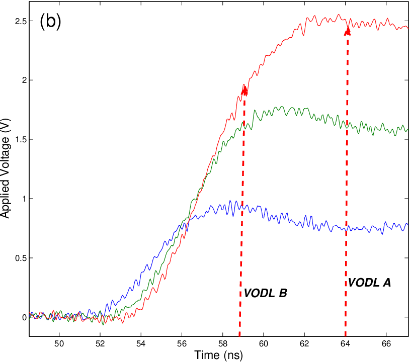
Another challenge is the optimization of VODL. Ref [13] assumed Eve could remap Alice’s encoded phase with . However, in our experiment, the relation among , , and is more complicated. As shown in Fig. 6, Alice’s phase modulation signals {, , } not only start at different times but also have different average rising times {6.12ns, 7.82ns, 9.47ns}. Furthermore, there is also an overshoot after the rising edge, and the time is different from each other. So, if we use different lengths of VODL to shift the pulse either to the rising edge or to the overshooting range, the pulse will not undergo proportional phase modulation. Eve’s remapping phase will be . These complicated phases will thus cause an effect of QBER as shown in Eqn. (1).
In our experiment, the optimal length of VODL was determined by minimizing the resulting QBER. We finally applied two optimal VODL (see Fig. 6(b)) to launch two types of practical phase remapping attack: VODL A: 4.65m and VODL B: 5.8m. Our attack strategy was the one discussed in Section II. Here, we remark two points: (1) from the time pattern graph in Fig. 4, the laser pulse is narrow enough to allow us to apply type 1 attack; (2) in type 1 attack, to make the remapping phase small enough, we still control the polarization of backward pulse orthogonal to the principal axis.
IV Experiment results
| 1.39 |
Some experimental parameters of our ID-500 commercial QKD system, including dark count rate , detector error rate , Bob’s overall quantum efficiency (including the detection efficiency of single photon detector), detection efficiency and mean photon number are listed in Table 1. Our transmission distance was a few meters. We repeated the measurement 10 million times for each state sent by Alice and the experimental results are shown in Table 2.
| Base0 | Base1 | Base2 |
| State | D1 | D2 | D1 | D2 | D1 | D2 | ||
|---|---|---|---|---|---|---|---|---|
| 617 | 168910 | 7068 | 174061 | 24841 | 156007 | |||
| 5843 | 167206 | 1074 | 179218 | 8557 | 170786 | |||
| 18096 | 153962 | 5285 | 174161 | 1239 | 176091 | |||
| 33260 | 135616 | 19770 | 160300 | 3530 | 173428 |
| (a) |
| Base0 | Base1 | Base2 |
| State | D1 | D2 | D1 | D2 | D1 | D2 | ||
|---|---|---|---|---|---|---|---|---|
| 734 | 171851 | 6617 | 166671 | 16311 | 158479 | |||
| 7435 | 165402 | 928 | 169814 | 2772 | 169669 | |||
| 16474 | 157385 | 3545 | 166427 | 1348 | 168924 | |||
| 26879 | 146917 | 8434 | 161575 | 2672 | 168078 |
| (b) |
QBER is analyzed as follows. First, we calculate QBER from the theoretical model discussed in Section II. The detecting probability of phase-coding BB84 QKD protocol is
| (3) | |||
where denotes the gating number [22]. Here, we subtract the dark counts number from each detector’s counts number to get the theoretical detecting probability.
If Eve introduces phase shift {0} (Base0) on the reference pulse to measure each state, the remapping phase and phase difference (i=1,2,3) are
| (4) | |||
Using data in Table 2, from Eqn. (4) and (1), we can get
| (5) | |||
The phase error fluctuations are mainly due to the imperfections of our experimental QKD system. From the results in Table 2, we can see that even though Eve uses Base0 to measure state {}, it still has about “” counts on Det1. These error counts are mostly from the imperfect interference between the signal pulse and the reference pulse. So, Eqn. (5) gives the theoretical QBERs introduced by Eve with perfect detection system.
Now, we calculate QBER via our direct experimental results. From Table 2, we can see the total counts (D1+D2) are almost identical, so Det1’s detecting probability for each state is proportional to D1. The QBERs can be calculated using data in Table 2:
| (6) | |||
| (7) | |||
It is surprising to see that if Eve utilizes the optimal strategy to combine two types of attack together and carefully chooses the the probability of each attack to ensure the distribution of bit “0” and bit “1” received by Bob is balanced, the overall QBER will be
| (8) |
Note that we used weak coherent pulse (WCP) source in our experiment. Before calculating the QBERs for single-photon (SP) source, we emphasize two facts: (1) the phase shift introduced by the phase modulator is independent of the source. If the source is a SP, the phase will be also remapped to {0, , , }. (2) Eve’s interference visibility is the same for SP and WCP. Now, assume that Eve introduces Base1 to launch attack and Det1’s detecting probability for each state is , i.e. {, , , }, Det1’s overall gain and QBERs for the two different sources are given by:
| (9) | |||
| (10) | |||
Using Eqn. (9-10) and data in Table 1 and 2, the overall QBER difference between SP and WCP for Eve’s optimal strategy (combine two types of attack as Eqn. (8)) is:
| (11) |
Therefore, in a practical SP BB84 QKD system, we can expect the QBER is =19.8%, which is lower than the tolerate security bound of 20.0% [14]. The security of SP BB84 QKD system is compromised. Eve can also combine the phase-remapping attack with a faked state attack together to substantially enhance its power [13]. Finally, we remark that even if we have only broken a practical SP BB84 QKD system, the security proofs of both WCP and SP QKD are based on the same assumptions. One key assumption (Alice prepares her states correctly) has been violated in our experimental demonstration. So the security proofs can not be directly applied to a practical QKD system.
V Conclusion
We conclude this paper with some general comments. First, let us consider countermeasures. In the “plug-and-play” QKD system, one specific countermeasure is the following: Alice carefully checks the arrival time of the reference pulse and the signal pulse by monitoring with her classical detector (CD in Fig. 3). From the time delay between the two pulses, she can find whether the time difference has been shifted by Eve, and thus counter Eve’s attack. Moreover, in our attack, Eve only sends two states to Bob. Alice and Bob can detect this attack by estimating the statistics of the four BB84 states. Note that, once a security loophole has been found, it is often easy to develop countermeasures. However, the unanticipated attacks are the most fatal ones.
Second, this paper mainly focuses on one key assumption in unconditional security proofs, i.e. Alice prepares the required states correctly. From a simple experimental demonstration, we show this assumption can be violated by our attack. So, we emphasize that, in a practical QKD system, Alice needs to experimentally verify she is applying the correct modulations on her states. One possible way in a general QKD system is: after encoding her random bits, Alice uses a beam splitter to split part of each strong modulated signal, and then use a detector, such as a power meter (rather than a single-photon detector), to implement a local measurement to directly verify whether she has performed the correct modulation. In order to achieve unconditional security with a practical QKD system, it is useful to perform such a verification experimentally. In the long term, it is important to work towards QKD with assumptions.
Third, Eve can also maximize her ability to eavesdrop by combining various attacks. For instance, she may combine the phase-remapping attack with the time-shift attack to exploit both the imperfections of Alice’s encoding system and Bob’s detection system. If she does so, the QBER might be reduced further. We remark that, it is impossible to remove all imperfections completely in practice. Instead of removing them, what we can do is to quantify them carefully. Once quantified, those imperfections may be taken care of in security proofs [5, 23]. As an example, mismatch in detection efficiency has been taken into account in the security proof of [24].
Finally, our demonstration of the phase remapping attack was done on a specific implementation of QKD. Notice, however that the implementation is the one widely used in commercial QKD systems [17]. Moreover, in a general class of QKD systems and protocols, our work highlights the significance for Alice to verify the correctness of her preparation. In practice, any QKD is done on a specific implementation and it has imperfections. If we can’t trust a specific implementation of QKD, one should never use QKD in the first place.
In summary, we have experimentally demonstrated a technologically feasible attack, where Eve can get full information and only introduces a QBER of 19.7%. A simple “intercept-and-resend” attack will normally cause a QBER of 25% in BB84. So, our result shows clearly an imperfection in the QKD implementation. The security of a single photon BB84 QKD system has been compromised. Specially, this is the first successful “intercept-and-resend” attack on top of a commercial bidirectional QKD system. The success of our attack highlights not only the importance for Alice to verify that she is encoding the right state during the encoding process, but also, more generally, the importance of verification of the correctness of each step of an implementation of a QKD protocol in a practical QKD system.
VI Acknowledgments
We are thankful for the preliminary work of Felipe Corredor, Eva Markowski, and Chi-Hang Fred Fung. Support of the funding agencies CFI, CIPI, the CRC program, CIFAR, MITACS, NSERC, OIT, and QuantumWorks is gratefully acknowledged.
References
- [1] C. H. Bennett and G. Brassard, Proceedings of IEEE International Conference on Computers, Systems, and Signal processing, pp. 175-179, IEEE New York (1984); A. K. Ekert, Physical Review Letters, 67 661 (1991)
- [2] N. Gisin, G. Ribordy, W. Tittel, and H. Zbinden, Reviews of Modern Physics, 74 145 (2002)
- [3] H.-K. Lo and Y. Zhao, Encyclopedia of Complexity and Systems Science, 8 7265, Springer New York (2009); V. Scarani, H. Bechmann-Pasquinucci, N. J. Cerf, M. Dušek, N. Lütkenhaus and M. Peev, Reviews of Modern Physics, 81 1301 (2009)
- [4] H.-K. Lo and H. F. Chau, Science, 283 2050 (1999); P. Shor and J. Preskill, Physical Review Letters, 85 441 (2000); D. Mayers, JACM, 48 351 (2001)
- [5] D. Gottesman, H.-K. Lo, N. Lütkenhaus, and J. Preskill, Quant. Inf. and Comput, 4 325 (2004); H. Inamori, N. Lütkenhaus, and D. Mayers, The European Physical Journal D-Atomic, Molecular, Optical and Plasma Physics, 41 599, Springer (2007)
- [6] N. Gisin, S. Fasel, B. Kraus, H. Zbinden, and G. Ribordy, Physical Review A, 73 22320 (2006)
- [7] V. Makarov, A. Anisimov, and J. Skaar, Physical Review A, 74 22313 (2006)
- [8] B. Qi, C.-H. F. Fung, H.-K. Lo, and X. Ma, Quant. Inf. and Comput., 7 73 (2007)
- [9] Y. Zhao, C.-H. F. Fung, B. Qi, C. Chen, and H.-K. Lo, Physical Review A, 78 42333 (2008)
- [10] A. Lamas-Linares and C. Kurtsiefer, Opt. Express 15, 9388 (2007)
- [11] V. Makarov, New Journal of Physics, 11 065003 (2009); V. Makarov, A. Anisimov, and S. Sauge, quant-ph, 0809.3408 (2008)
- [12] V. Scarani and C. Kurtsiefer, quant-ph, 0906.4547 (2009); B. Qi, L. Qian, and H.-K. Lo, quant-ph, 1002.1237 (2010)
- [13] C.-H. F. Fung, B. Qi, K. Tamaki, and H.-K. Lo, Physical Review A, 75 32314 (2007)
- [14] D. Gottesman and H.-K. Lo, IEEE Transactions on Information Theory, 49 457 (2003); H. Chau, Physical Review A 66 60302 (2002)
- [15] A. Muller, T. Herzog, B. Huttner, W. Tittel, H. Zbinden, and N. Gisin, Appl. Phys. Lett., 70 793 (1997)
- [16] T. Nishioka, H. Ishizuka, T. Hasegawa, and J. Abe, IEEE Photonics Technol. Lett., 14 576 (2002); B. Qi, L.-L. Huang, H.-K. Lo, and L. Qian, Proceedings of IEEE International Symposium on Information Theory, pp. 2090-2093, IEEE New York (2006)
- [17] http://www.idquantique.com; http://www.magiqtech.com
- [18] After the Mach-Zehnder interferometer, if the phase difference between reference and signal pulse is (0), detector1 (detector2) clicks.
- [19] A. Yariv and P. Yeh, Photonics: optical electronics in modern communications (sixth edition), Oxford University Press (2007)
- [20] The relative magnitude ratio is experimentally tested by appling different voltages on Alice’s phase modulator (PMA in Fig.3) to modulate the signal pulses with the two polarization directions (adjusted by PC in Fig.3). From the data of applied voltages and modulating phases, we got the relative ratio is about 1 : 3. Ref. [19] gives the parameters of LiNbO3 phase modulator and the relations between phase modulation and the parameters. The relative ratio is 9.6 : 30.9 (see Section 9.2 and Table 9.2 of Ref [19]).
- [21] If the polarization is not properly controlled by PC, after Alice’s modualtion, the original linear polarization state of the signal pulse will change to circular or ellipse polarization state. So, when the signal pulse returns back and passes through Eve’s PBS (see Fig.3), part of it will wrongly go to the long arm instead of the short arm. Since the Detector (Det in Fig.3) is gated, this part will hit the Detector at a wrong time and thus cannot be detected.
- [22]
Here, we repeated the measurement 10 million times for each state.
Notice that, in order to reduce the after-pulsing probability, an
external dead time has been introduced to both detectors after the
detection of a photon by a detector. On average, after each
detection event, the following around 46 gating signals will be
blocked. So, the total gating number can be estimated by
(12) - [23] Ø. Marøy, L. Lydersen, and J. Skaar, quant-ph, 0903.3525 (2009)
- [24] C.-H. F. Fung, K. Tamaki, B. Qi, H.-K. Lo, and X. Ma, Quant. Inf. and Comput., 9 131 (2009)