A. Piccolroaz
Affiliation: Dipartimento di Ingegneria Meccanica e
Strutturale, Università di Trento,Via Mesiano 77, I-38050 Trento, ItaliaG. Mishuris
Affiliation:
Institute of Mathematical and Physical Sciences, Aberystwyth University, Ceredigion SY23 3BZ, Wales U.K.,A.B. Movchan
Affiliation:
Department of Mathematical Sciences, University of Liverpool, Liverpool L69 3BX, U.K.
Abstract
We consider the perturbation problem of a Mode III interfacial crack. The perturbation is of geometrical type and can be both
perturbation of the crack faces and perturbation of the interface, which can deviate from the initial straight line configuration.
Asymptotic formulae are derived for the first-order perturbation of the stress intensity factor. It is shown that, due to the
unsymmetrical nature of the problem, the Mode III skew-symmetric weight function derived in Piccolroaz et al. (2009) is essential for
the derivation of the correct asymptotic formulae.
To illustrate the method, we present the numerical results for different geometrical perturbations of a half-plane interfacial
crack in an infinite bimaterial structure. Discussion on the extension of the method to finite bodies is also presented.
1 Introduction
Modelling of interfacial cracks was addressed in the fundamental papers by Willis (1971) and Hutchinson et al. (1987).
Oscillatory asymptotics of displacement and stress fields near the crack edges represent an important feature of interfacial
cracks in vector problems of elasticity. Singular integral equations for the displacement jump across the crack take into
account the full coupling between the normal and shear modes of loading.
The notion of weight functions for cracks, as stress-intensity factors associated with a point force load, was introduced in
Bueckner (1985, 1989). Another approach, viewing weight functions as special singular solutions of homogeneous problems for
cracks, was used in Willis and Movchan (1995). Analysis of weight functions, represented by special singular solutions of
the homogeneous problem for an interfacial crack was performed in Lazarus and Leblond (1998) and Antipov (1999).
Further studies, involving both symmetric and skew-symmetric weight functions, are included in Bercial-Velez et al. (2005) and
Piccolroaz et al. (2007). In particular, as the three-dimensional crack advances, the crack front deviates, and for the case of
in-plane deviations the paper Piccolroaz et al. (2007) incorporates the first-order analysis of the weight functions based
on the full solution of the corresponding matrix Wiener-Hopf equation. It has been shown by Piccolroaz et al. (2009) that the
lack of symmetry inherent in the interfacial crack problem induces the appearance of a skew-symmetric component of the weight
functions, so that, for instance, the skew-symmetric loads generate non-zero stress intensity factors even in the case of two
dimensions (plane strain, plane stress or antiplane shear).
We note that the problem of finding the variation of the stress intensity factors induced by a small geometrical perturbation of a
plane crack placed at the interface between two dissimilar elastic materials requires the use of not only the symmetric weight
functions but also of the skew-symmetric components. This statement is valid not only for a full vector problem, but it is also true
for relatively simple anti-plane shear formulations. This is shown in the present paper with reference to the case of Mode III
deformation.
We consider both perturbation of the crack faces and of the interface, so that, in its perturbed state, the crack faces occupy
the lines
whereas the interface occupies the line
Here, we assume that the functions and their derivatives vanish within a finite neighbourhood of the crack tip.
Such perturbation is referred to as the regular perturbation of the boundary.
Using the symmetric and skew-symmetric weight functions for the interfacial crack, we derive asymptotic formulae for the perturbed
stress intensity factor, which characterize the stress in the vicinity of the crack tip.
The paper is organized as follows. The formulation of the problem and the governing equations are outlined in Section 2.
Section 3 introduces the symmetric and skew-symmetric weight functions for the interfacial crack; the same section outlines
the regular perturbation asymptotic procedure. An illustrative example and applications of the asymptotic formulae are included in
Section 4.
2 Problem formulation
We consider a twodimensional bimaterial structure made of two dissimilar materials, joined along a plane interface, see
Fig. 1. The two materials are assumed to be linear elastic and isotropic, with elastic moduli denoted by
(shear modulus) and (Poisson’s ratio). A plane crack is placed along the interface, which is assumed to be perfect, so that
the displacement and traction components are continuous across the interface .
The cracked body is loaded by out-of-plane tractions: along the outer boundary
, and along the crack faces , where denotes the
displacement component along . The loading is self-balanced in terms of both principal force and moment vectors
(1)
Suppose that the plane crack faces and the plane interface are slightly perturbed: the perturbation is denoted by
with supports for the crack faces and with support for the interface, where is
a small parameter. We are interested in the calculation of the corresponding perturbation of the stress intensity factor .
Figure 1: Geometry of the problem
The problem is then formulated in terms of the Laplace equation
(2)
with boundary conditions:
(3)
(4)
and interface conditions
(5)
We assume that the loading along the crack faces is separated from the supports .
3 Solution of the perturbation problem by means of symmetric and skew-symmetric weight functions
The solution of the perturbed problem, , can be expanded for small as follows
(6)
where is the solution of the unperturbed problem () and is the first-order
variation of the solution with respect to .
3.1 Model problem for
The model problem for is obtained by taking the leading order asymptotics of the perturbed problem as ,
so that must satisfy the Laplace equation (2) with the boundary and interfacial conditions
(3) – (5) where the boundaries and are replaced by
and , respectively, see Fig. 2.
Figure 2: Model problem for
The solution with locally bounded elastic energy and vanishing at infinity can be easily found by means of Mellin transform in polar
coordinates. The Mellin transforms for the displacement vector and the stress tensor are defined as follows
(7)
and they are represented by analytic functions in the strips and , respectively.
Correspondingly, the inverse transforms are
(8)
where lie in the respective intervals.
With taking into account all boundary conditions, one can obtain the solution in the form (see Appendix A.1 for details):
(9)
Introducing the symmetric and skew-symmetric loading, and
respectively, we obtain
(10)
The stress components are given by
(11)
(12)
This allows to obtain the two-terms asymptotics of tractions ahead of the crack tip and crack opening:
(13)
(14)
respectively, where
(15)
(16)
in which is the contrast parameter.
3.2 Model problem for
To obtain the model problem for we will follow the procedure described in Movchan and Movchan (1995) and
expand the term along and , and also
along .
We obtain:
(17)
(18)
and
(19)
Figure 3: Model problem for
Therefore the model problem for (see Fig. 3) is formulated in terms of the Laplace equation
(2) with boundary conditions
(20)
along the boundary ,
(21)
along , and the interfacial conditions
(22)
(23)
Note that the right-hand sides in (21), (23) can be interpreted as “effective” loading
along the crack faces and along the interface, respectively, whereas (22) is a prescribed discontinuity of
displacement along the interface.
3.3 The reciprocity identity and evaluation of the stress intensity factor
The integral representation of the stress intensity factor can be obtained by application of the Betti identity, in
a way similar to Piccolroaz et al. (2007). The formula is extended here to include the case of imperfect interface with prescribed
discontinuities of displacement and traction .
The reciprocity identity reads
(24)
where and are the symmetric and skew-symmetric Mode III weight functions and
the corresponding traction (see Piccolroaz et al., 2009),
Note that , are average and jump of the prescribed loading on the crack
faces, whereas , are the prescribed discontinuities of traction and displacement
along the interface.
The asymptotic procedure described in Piccolroaz et al. (2009) allows us to obtain the integral formula for the computation of
as
(29)
which, upon substitution of (25) and (26), simplifies to
(30)
Note from (30) that the traction discontinuity , prescribed along the interface, does not contribute
to the stress intensity factor. This is because the weight function is identically zero for .
Now, we consider the asymptotic expansion of with respect to as follows
(31)
and make use of the integral formula (30) to compute both the leading term and the first order variation .
It is evident that the leading term corresponds to the unperturbed problem () and was defined in (15).
The second term corresponds to the model problem described in Sec. 3.2 and can be written as
(32)
where and denote the variations due to the perturbation of the crack faces and of the interface,
respectively.
where both jump and average notations are standard and
(35)
in which the supports of the functions belong to the corresponding boundaries and .
Integrating by parts the first integral (33) we get
(36)
in which, from the solution described in (9), we can write for :
(37)
where , and for :
(38)
4 An illustrative example
To illustrate the perturbation method described above, we show in this section numerical results concerning the perturbation of both
crack faces and interface geometry in the case of an interfacial half-plane crack in an infinite bimaterial structure, see Fig. 4.
The crack faces are loaded by a “three-point” loading system consisting of: a point force acting upon the upper crack face at a
distance behind the crack tip and two point forces acting upon the lower crack face at a distance and behind
the crack tip, see Fig. 4. In terms of the Dirac delta function , the loading is then given by
(39)
(40)
or, in terms of symmetric and skew-symmetric parts, by
Here and in what follows we everywhere assume without lost of generality that .
Figure 4: Illustrative example
Applying the Mellin transform, we obtain
(41)
(42)
so that, the zero-order stress intensity factor, corresponding to the unperturbed problem, is given by
(43)
4.1 Perturbation of crack faces
Let us consider first the perturbation of the crack faces, defined by the two functions and , which have the form
(44)
and have supports in the intervals . Note that the conditions must be
satisfied in order to have supports of the functions separated from the loading.
where the term in the integrand can be computed using (37), to obtain
(46)
in which
(47)
(48)
where the sign depends on whether .
The integrals and can be evaluated in closed form (see for instance Gradshteyn and Ryzhik, 2007):
(49)
(50)
One can check that
(51)
(52)
(53)
(54)
The estimations show that both functions and are singular for small argument values and also
tends to infinity for large positive values of its argument.
The integral formula for is
(55)
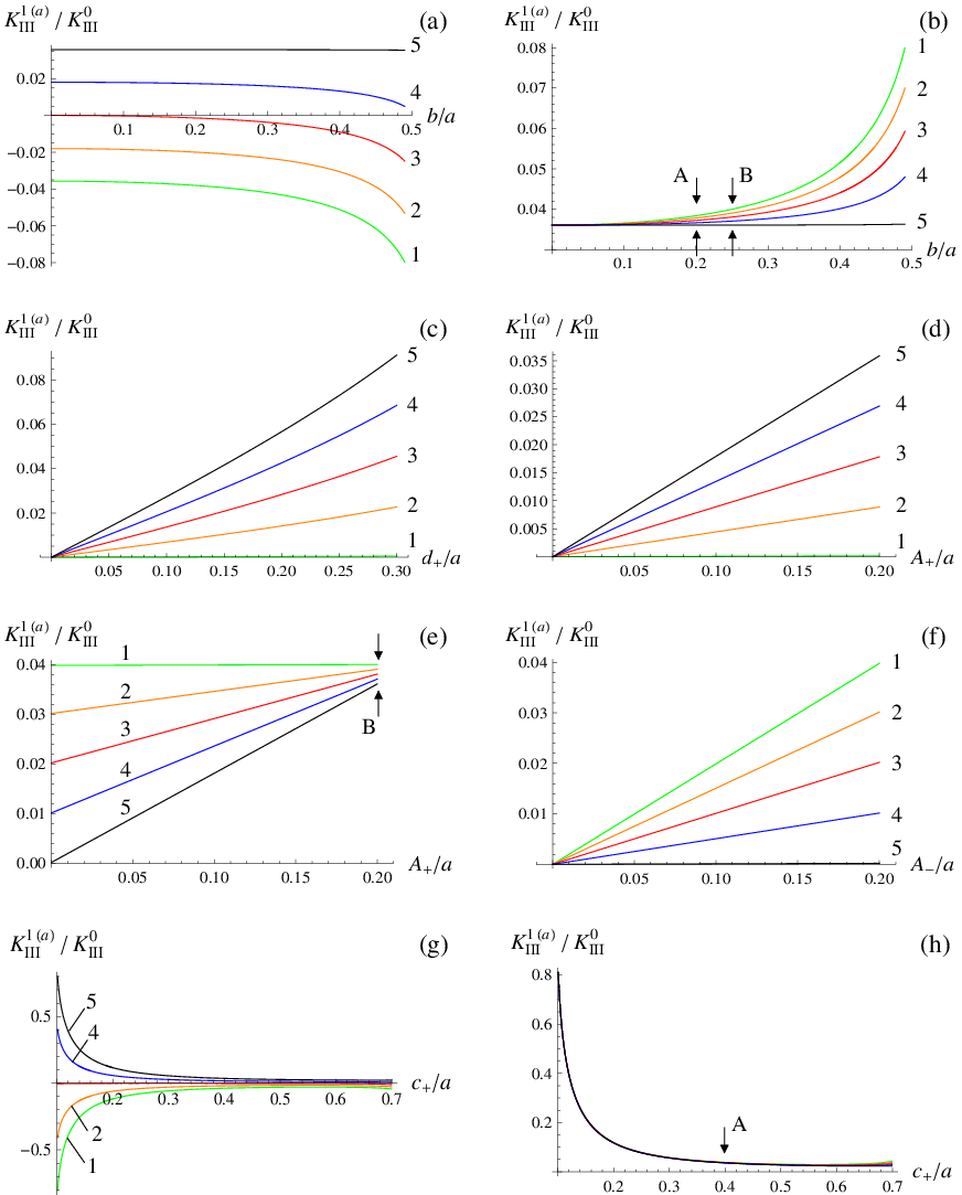
Numerical results for different values of parameters are shown in Fig. 5. We note that for the regular perturbation geometry,
the integrand in (55) may allow for a singularity not higher than for admissible values of the
geometrical parameters
Figure 5: Numerical results for perturbation of the crack faces: (1 - green) ,
(2 - orange) , (3 - red) , (4 - blue) , (5 - black) .
For parts (a) and (b) of this figure, we use skew-symmetric and symmetric perturbation of the crack faces, respectively. The geometrical
parameters are shown in Table 1.
The load is produced by point forces applied to the crack surfaces, as shown in Fig. 4.
A certain asymmetry is introduced in the applied load: one point force is applied on the upper crack face, whereas two smaller point
forces at shifted positions are applied on the lower crack face; the total load is self-balanced, and the asymmetry is characterised
by the ratio representing the normalised distance between the two point forces on the lower crack face. Diagrams in
Fig. 5a,b show the first-order correction in the stress intensity factor for the cases of different asymmetry in the
applied load and different values of the contrast parameter When the perturbation of the crack
faces is skew-symmetric (see part (a)) the first-order variation in the stress intensity factor becomes zero for the case when the
materials above and below the crack are equal and when , as expected. For the case of a bi-material interface, the sign of
the perturbation depends on the material allocation and the stress intensity factor is shown to be sensitive to the asymmetry in the
applied load. It is also visible on the diagrams of Figs. 5a and 5b that when the two forces are applied to the
crack face on the stiffer half-plane (see the curve with the label ) the sensitivity to the asymmetry in the applied load becomes
insignificant.
In Fig. 5c, we show the first-order correction for the stress intensity factor for the case when the lower face of the crack
is not perturbed whereas the upper face has sustained a smooth perturbation with increasing support. It is shown that the increase in
the size of the perturbation region leads to the increase in the stress intensity factor. It is also noted that the case of a soft upper
half-plane, corresponding to the perturbed side of the crack, leads to the larger change in the stress intensity factor.
In Figs. 5d and 5e, we show the cases when the lower face of the crack is not perturbed (as in Fig. 5d)
or perturbed with fixed amplitude (as in Fig. 5e), whereas the upper face is perturbed with the variable amplitude. It is shown
that the correction for the stress intensity factor (initially zero for case 5d, corresponding to the unperturbed geometry)
grows linearly as the slope is different for different materials, following the same pattern as in the case 5c. Note that the
values marked by the arrows in Fig. 5e, corresponding to , are identical to the values marked by the arrows in
Fig. 5b, corresponding to , since the two cases correspond to the same geometrical configuration.
Fig. 5f shows the case when the upper face of the crack is not perturbed whereas the lower face is perturbed with the variable
amplitude, a situation opposite to the case 5d. These computations confirm the conclusion that the variation of the stress
intensity factor is stronger when the perturbation is applied to the softer material.
In Fig. 5g we show the results obtained for the skew-symmetric perturbation of the crack faces “moving” along the crack,
so that the perturbed boundary becomes close to the region of applied tractions for and to the crack tip for
. It is shown that the highest impact on the SIF appears when the perturbation is located near the crack tip,
whereas a slight increase is observed when the perturbation appears near the acting load. It is also noted that for the homogeneous
material this contribution is negligibly small. Fig. 5h corresponds to the case when the “moving” perturbation of the
crack faces is symmetric. In this case, the influence of material parameters appears to be small (see also Fig. 5b, where
the influence of material parameters is enlarged by the refined scale) and the effect on the SIF increases considerably when the
perturbation is approaching the crack tip, even for homogeneous material.
4.2 Perturbation of the interface
We consider now the perturbation of the interface, defined by the function , which has the form
(56)
and has support in the interval . From eqs. (34) and (37), we obtain
(57)
where
(58)
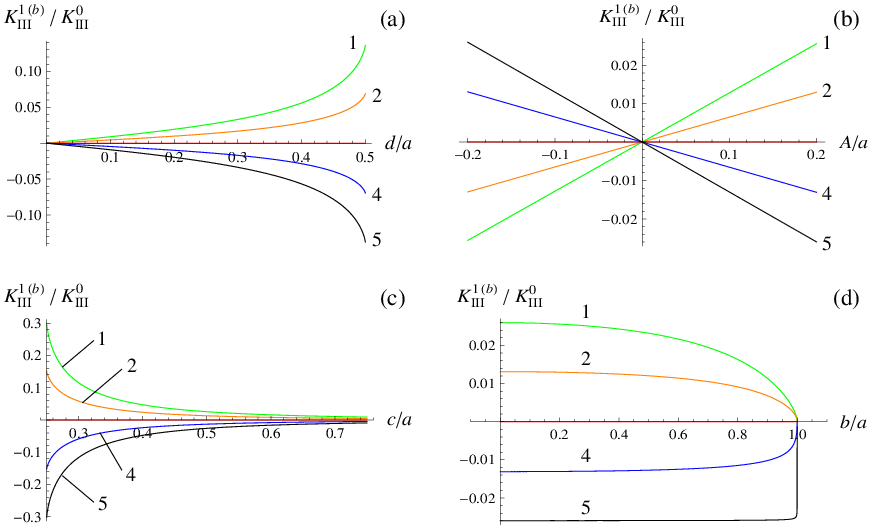
Numerical computations of the perturbation of the stress intensity factor for different values of parameters are shown in
Fig. 6. The geometrical parameters characterising the perturbations are given in Table 2.
Figure 6: Numerical results for perturbation of the interface:
(1 - green) , (2 - orange) , (3 - red) , (4 - blue) , (5 - black) .
First, we note that the case of corresponds to zero perturbation of the stress intensity factor, since this situation corresponds to
a straight crack in a homogeneous medium. In part (a) of the figure, we show the case when the amplitude of the perturbation is fixed, whereas
the width of the perturbation region is subject to change. As expected, the increase in the size of the perturbation region leads to the increase
of the magnitude of the stress intensity factor. If the tractions are applied to the crack faces at a finite distance from the crack tip
then the asymmetry in the applied load does not give a substantial influence to the magnitude of the perturbation of the stress
intensity factor. On the part (b) of the figure, we look at the stress intensity factor as a function of the amplitude of the perturbation
of the interface ahead of the crack. As expected, this dependence is linear, and the asymmetry of the applied load does not give much
influence on the results of the computations. The diagram (c) of the figure corresponds to the case when the perturbation region of
a fixed width and amplitude is displaced along the interface ahead of the crack. As expected, when the perturbation region moves towards
the crack tip the magnitude of the perturbation of the stress intensity factor is increasing. Both cases, (a) and (c) show that the
perturbation of the stress intensity factor is bounded, as predicted for the case of the regular perturbation of the interface.
The last diagram (d) in Fig 6 illustrates the influence of the asymmetry of the applied load on the perturbation of the
stress intensity factor. Namely, we consider the extreme situations when one of the forces applied to the lower face of the crack is
allowed to approach the crack tip. In this case, grows and correspondingly one can see the ratio of
decreasing. We also note that the curve with the label corresponds to the stiff material in the lower
half-plane, and hence the change in the stress intensity factor is visible only for small distance between the region of loading and
the crack tip.
5 Discussions and conclusions
In this paper, we have illustrated the use of the skew-symmetric weight functions in evaluation of the stress intensity factors for
regularly perturbed interfacial cracks in problems of anti-plane shear. The influence of asymmetry of the applied load as well as
geometrical perturbations has been shown by the numerical simulations based on the explicit asymptotic formulae. Although the computations
were presented for the case of a crack in an infinite two-phase plane, the symmetric and skew-symmetric weight functions for a finite
domain can be constructed by a straightforward superposition of the infinite plane singular solution and an auxiliary solution with the
finite energy constructed for the finite domain. The asymptotic algorithm for evaluation of the stress intensity factors, presented here,
equally works for regularly perturbed domains of finite size.
References
[1]
Antipov, Y.A.,
An exact solution of the 3-D-problem of an interface semi-infinite plane crack,
J. Mech. Phys. Solids47, 1051-1093, (1999).
[2]
Bercial-Velez, J.P., Antipov, Y.A. and Movchan, A.B.,
High-order asymptotics and perturbation problems for 3D interfacial cracks,
J. Mech. Phys. Solids53, 1128-1162, (2005).
[3]
Bueckner, H.F.,
Weight functions and fundamental fields for the penny-shaped and the half-plane crack in three-space,
Int. J. Solids Struct.23, 57-93, (1985).
[5]
Gradshteyn, I.S. and Ryzhik, I.M.,
Table of integrals, series, and products.
Academic Press, London, (2007).
[6]
Hutchinson, J.W., Mear, M.E. and Rice, J.R.,
Crack paralleling an interface between dissimilar materials,
ASME J. Appl. Mech.54, 828-32, (1987).
[7]
Lazarus, V. and Leblond, J.B.,
Three-dimensional crack-face weight functions for the semi-infinite interface crack - I: Variation of the stress
intensity factors
due to some small perturbation of the crack front,
J. Mech. Phys. Solids46, 489-511, (1998).
[8]
Movchan, A.B. and Movchan, N.V.,
Mathematical modeling of solids with nonregular boundaries,
CRC-Press, (1995).
[9]
Piccolroaz, A., Mishuris, G. and Movchan, A.B.,
Evaluation of the Lazarus-Leblond constants in the asymptotic model of the interfacial wavy crack,
J. Mech. Phys. Solids55, 1575-1600, (2007).
[10]
Piccolroaz, A., Mishuris, G. and Movchan, A.B.,
Symmetric and skew-symmetric weight functions in 2D perturbation models for semi-infinite interfacial cracks,
J. Mech. Phys. Solids57, 1657-1682, (2009).
[11]
Willis, J.R. and Movchan, A.B.,
Dynamic weight functions for a moving crack. I. Mode I loading,
J. Mech. Phys. Solids43, 319-341, (1995).
[12]
Willis, J.R.,
Fracture mechanics of interfacial cracks.
J. Mech. Phys. Solids19, 353-368, (1971).
Appendix A APPENDIX
A.1 Representation in terms of Mellin transform
In this section we summarize the solution of the Mode III loading of the interfacial crack, by means of Mellin transform.
The problem is formulated in terms of the Laplace equation
(A.1)
subject to the boundary conditions along the crack faces ()
(A.2)
and the transmission conditions along the imperfect interface with presribed discontinuities of displacement and traction ()
(A.3)
(A.4)
In polar coordinates the Mellin transforms for the displacement vector and the stress tensor with locally bounded elastic energy are defined
as follows
(A.5)
and they are represented by analytic functions in the strips and ,
respectively, where (), are constants related
to the behaviour of the solution at the crack tip and at infinity, namely
(A.6)
Correspondingly, the inverse transforms are
(A.7)
where and .
Applying the Mellin transform to the Laplace equation,