On the Non-Coherent Wideband Multipath Fading Relay Channel
Abstract
We investigate the multipath fading relay channel in the limit of a large bandwidth, and in the non-coherent setting, where the channel state is unknown to all terminals, including the relay and the destination. We propose a hypergraph model of the wideband multipath fading relay channel, and show that its min-cut is achieved by a non-coherent peaky frequency binning scheme. The so-obtained lower bound on the capacity of the wideband multipath fading relay channel turns out to coincide with the block-Markov lower bound on the capacity of the wideband frequency-division Gaussian (FD-AWGN) relay channel. In certain cases, this achievable rate also meets the cut-set upper-bound, and thus reaches the capacity of the non-coherent wideband multipath fading relay channel.
I Introduction
The general relay channel is among the smallest building blocks of communication networks, yet its capacity is still an open problem. Bounds on the capacity of the general relay channel, and the capacity of some particular classes of relay channels, have been derived in the past [1]. In particular in [2], the expression of the cut-set upper bound from [1], and the generalized block-Markov lower bound were derived for the case of the frequency-division additive white Gaussian noise (FD-AWGN) relay channel, where the source and the relay transmit in different bands. However, despite a plethora of recent works proposing cooperative strategies for wireless relaying networks and studying their performance in the high SNR regime, the capacity of the multipath fading relay channel remains unknown. Specifically, few works [3] analyzed the fading relay channel in the low SNR regime.
This paper focuses on analyzing the multipath fading relay channel in the non-coherent setting, where neither the source, nor the relay, nor the destination have channel state information (CSI), and in the wideband regime, alternatively named low SNR regime. Indeed, in the wideband regime, power is shared among a large number of degrees of freedom, making the SNR per degree of freedom low. Thus the wideband regime is power limited, but not interference limited on the contrary to the high SNR regime. In the wideband regime, the capacity of the point-to-point AWGN channel [4] and the capacity of the point-to-point non-coherent multipath fading channel [5] were shown to be both equal to the received SNR: . Moreover, in the wideband limit of fading channels, spread-spectrum signals were shown to achieve poor performance, whereas peaky signals in time and frequency, such as low duty-cycle FSK, along with non-coherent detection, were shown to be capacity optimal [6]. The capacity of the point-to-point multiple input multiple output (MIMO) channel in the wideband limit was addressed in [7]. In particular, for the SIMO channel with two receive antennas with respective gains and , the capacity is . Results on multiple user channels in the wideband limit include, the capacity region of the AWGN Broadcast Channel (BC) [8], for which time-sharing was shown to be optimal, and the capacity region of the AWGN Multiple Access Channel (MAC) [9], for which FDMA allows all sources to achieve their point-to-point interference-free capacity to the destination.


Some observations can be drawn from previous works on point-to-point and multiple user channels in the wideband regime: the capacity in the multipath fading case is the same as in the AWGN case, it can be reached in a non-coherent setting, and interference is not an issue. Coming back to the non-coherent multipath fading relay channel in the wideband regime, two questions naturally arise
- •
Can the FD-AWGN lower bound [2] be achieved in the non-coherent multipath fading case?
- •
Can the cut-set upper-bound [1] be reached?
Note that in the wideband regime, considering the FD channel is relevant and meets the relay half-duplex constraint. This paper addresses these questions through three main contributions:
- 1.
A hypergraph model of the wideband multipath fading relay channel is proposed.
- 2.
The hypergraph min-cut is shown to be achieved in the non-coherent wideband multipath fading relay channel by a peaky frequency-binning scheme.
- 3.
The hypergraph min-cut is shown to coincide with the generalized block-Markov lower bound on the capacity of the wideband FD-AWGN relay channel, and in certain channel configurations with the cut-set upper-bound, in which case it is equal to capacity.
The rest of the paper is organized as follows. In Section II, the hypergraph model of the wideband multipath fading relay channel is described, and the achievable hypergraph min-cut is compared with bounds on the capacity of the wideband FD-AWGN relay channel. The non-coherent scheme achieving the hypegraph min-cut is described in Section III, while its correspondence with the hypegraph model is detailed in Section IV, leading to the concluding Section V. Finally, the proof of Theorem 1 is provided in Appendix A.
II System model and main results
Notations: and denote the sets of non-negative integers, and real numbers, respectively. Let , the set of non-negative integers less or equal to is denoted . The subset of is denoted by . Let , . Let be a set, the indicator function is defined by if , if . is the probability of event A, is the statistical expectation operator, and is means that is a circularly symmetric complex Gaussian random variable with mean and variance .
II-A Wideband multipath fading relay channel
Consider the three-node network in Figure 1(a), where the source S, the relay R and the destination D are equipped with a single antenna. Source and relay are assumed to have average power constraints in the time-continuous channel model of and Joules/s respectively. We assume that S, R and D have no channel state information (CSI), thus the multipath channel is considered in the non-coherent regime. In order to respect the half-duplex constraint at the relay, we assume that S and R transmit in two different frequency bands of respective width and . During each temporal block of duration , S transmits a new codeword which R and D receive in the first frequency band; R performs some transformation on the signal received from S in the previous block and relays it to D in the second frequency band; D decodes a new codeword by processing the signals it received from S and R.
As in [6] the continuous-time multipath fading channel between transmitter and receiver is represented by the impulse response
| (1) |
where is the number of paths, and and are the gain and delay of path at time . For the sake of simplicity, we assume that all channels , , have similar coherence-time and delay-spread . Moreover we consider a block-fading model where the processes and have constant values and over intervals . Furthermore, the processes and are assumed to be independent, stationary and ergodic. Finally, let , we assume a non-symmetric network, with stationary total channel gains , , .
A signal transmitted in channel leads a received signal , where is a white Gaussian noise process with power spectral density .
As the band grows large, the capacity of the point-to-point non-coherent wideband multipath fading channel is equal to the received SNR [6]. Thus, the capacities of the point-to-point wideband channels between the source and the destination, the source and the relay, and the relay and the destination are respectively , , and .
II-B Hypergraph model and main results
In this section, we introduce a hypergraph model of the wideband multipath fading relay channel, and gather our main results in Theorem 1. More precisely, we show that the hypergraph min-cut is achieved by a non-coherent relaying scheme based on peaky signals, which is described in details in Section III, and we compare the hypergraph min-cut with bounds on the capacity of the FD-AWGN relay channel.
The proposed hypergraph model of the wideband relay channel is depicted in Figure 1(b). A hyperedge connects a transmitting node to several receiving nodes. A message transmitted over a hyperedge at a rate below its capacity can be decoded reliably by all the receiving nodes. Messages transmitted over disjoint hyperedges are independent. This hypergraph model of the relay channel is motivated by the broadcast nature of the wireless link: when a source transmits a signal over the wireless link, several receiving nodes can overhear the signal and extract some of the information transmitted by the source. The hypergraph model allows to clarify the correlation between the pieces of information decoded at different receiving nodes, by breaking the wireless link from a transmitting node into a set of hyperedges carrying independent messages. In Figure 1(b), the blue hyperedge represents a reliable channel from the source to both the relay and the destination with capacity , while the red and black edges represent extra reliable channels to the relay only with capacity , and to the destination only with capacity , respectively. Note that the black channel cannot coexist simultaneously with the red and blue channels. Finally, the green edge represents a reliable channel from the relay to the destination with capacity .
Theorem 1
Consider the non-coherent wideband multipath fading relay channel, described in Section II. When the system bandwidth grows large,
- 1.
a lower bound on the capacity is provided by the min-cut on the hypergraph model
(2) - 2.
- 3.
in the case where and , this achievable rate (2) is equal to the FD-AWGN cut-set upper-bound , and it is therefore the capacity of the non-coherent wideband multipath fading channel.
The proof of in Theorem 1 is provided in Appendix A. We now address 2) and 3). The cut-set upper bound, and the generalized block-Markov lower bound on the capacity of the FD-AWGN relay channel were derived in [2]. When the system bandwidth grows large, the cut-set upper bound converges to
| (3) |
and the generalized block-Markov lower bound converges to
| (4) |
Comparing (2) and (4) shows that the lower bounds on the capacity of the non-coherent multipath fading relay channel and the FD-AWGN channel coincide in the wideband limit when the channel is underspread (). This justifies 2) in Theorem 1, and shows that the hypergraph model is also valid in the FD-AWGN case.
In the case where and the channel is underspread (), the bounds (2), (4) and (3) coincide. The capacity of the multipath fading relay channel with infinite bandwidth cannot exceed the cut-set upper bound of the infinite bandwidth AWGN relay channel. We can then conclude that is the capacity of the non-coherent wideband multipath fading channel in that case, as stated in 3) in Theorem 1.
III Relaying scheme achieving the min-cut
In this section, we describe the non-coherent scheme which achieves the hypergraph min-cut in the multipath fading case.
III-A Peaky Signaling at Source
Let , and be positive integers such that the codebook size at source is . Consider a couple of independent random integers such that , . Then the Euclidian division theorem ensures that there exists a unique source message such that . The representation of as a couple has a binning interpretation. Indeed, the messages can be grouped into bins of messages. The integer represents the bin index of message , while is the index of message within bin , as illustrated in Figure 2. For , the -th bin is denoted and contains the messages .

During the first block of the cooperative transmission scheme, the source transmits a message using the peaky-signaling scheme in [6], which was shown to achieve capacity in the wideband regime, and that we recall briefly in this section. The transmission scheme is based on Frequency Shift Keying (FSK) and low-duty cycle, and is therefore peaky both in frequency and time. We denote by the duty-factor, representing the fraction of time during which the source actually transmits power. If the source transmits power during , then the time separating two successive transmissions is . Using FSK the transmitted signal corresponding to the -th message is given in the baseband by a sinusoid at frequency with power
| (5) |
where the transmission duration is chosen to be shorter than the coherence time . Frequencies are taken to be integer multiples of , leading to a minimum bandwidth for a codebook size .
During the interval the processes and are constant, thus the signal received by the relay, when message is sent, is given by:
where is the complex gain of the source-relay channel during .
Similarly, we define the complex gain for the source-destination channel and the signal received by the destination during , The source repeats the transmission of a symbol times over disjoint time intervals to obtain diversity. Both the relay and the destination receive the signals corresponding to message during the first temporal block of total duration .
To transmit a codeword carrying nats of information, an average power is used, and the source rate is given by . Note that the source rate can be written , with and .
III-B Processing at Relay
Upon reception of the source signals, the relay first decodes the bin index , then it forwards to the destination using peaky signaling. Note that if the number of bins was set to single bin, this would render the relay unused, and correspond to a direct transmission from S to D.
Phase 1: Decoding by correlating
The relay correlates the received signal against each frequency , forming the correlations
| (6) | |||||
where is the complex gain in interval , are i.i.d. circularly symmetric complex Gaussian random variables with unit-variance. By modeling assumption, are i.i.d. complex random variables. Assuming a large number of paths, can be modeled by i.i.d. circularly symmetric complex Gaussian random variables with -mean and variance . Then for each , are i.i.d. with variances
| (7) |
Note that for all . The relay decoder builds the decision variables
| (8) |
which for all are i.i.d. These decision variables are compared with the threshold , with to determine the set of bins containing at least one frequency above threshold
| (9) |
If only contains a single bin , the relay decodes , otherwise it declares an error.
Phase 2: Forwarding the bin index
If the relay has not declared an error at the end of Phase 1, then it forwards the bin index to the destination using peaky FSK in the second frequency band, with duty cycle and frequencies multiple of . Similarly to the source, the relay repeats times the transmission of over disjoint intervals of duration for diversity. In the -th interval, during the fraction of time where the relay signal is non-null, the signal is given by .
During the interval , of length , the signal received by the destination, corresponding to the -th relay signal, can be written , where is the complex gain of the relay-destination channel. To transmit a codeword carrying nats of information, a minimum bandwidth and an average power are used, and the relay rate is given by .
III-C Decoding at Destination
At the end of the second phase, the destination has received signals corresponding to the same message , half coming from the source, and half being the retransmissions from the relay. The destination first processes the signal from the relay to decode the bin index , then the signal from the source to decode the remaining index .
Step 1: Decoding the bin index
Similarly to (6), the destination correlates the signals from the relay against each of the frequencies in the second band, to form the correlations , for , and , given by
where are i.i.d. . Assuming a large number of paths, are modeled by i.i.d. random variables. Then, for each , the variables are i.i.d. with variances . The destination compares the decision variables with the threshold and builds the set
| (10) |
If , the destination decodes , otherwise it declares an error.
Step 2: Decoding the index
If the destination has not declared an error at the end of Step 1, it can proceed with the decoding by processing the signal it received from the source in the previous block. The destination uses to locate the bin of frequencies containing the source message in the signal . The destination correlates the messages it received from the source against the frequencies in to form the correlations , for , and
| (11) |
where are , and for each , the variables are i.i.d. with variance . It should be pointed out that the relayed signal allows the destination to reduce the dimension of the space in which it looks for the source message . More precisely, the relayed message allows the destination to reduce the number of noisy frequencies, to which it needs to compare the signal , from to . This observation is critical in the wideband regime where performance is mainly impaired by noise. For , the destination builds the decision variables . By comparing them with , it builds the set
| (12) |
If , the destination decodes , otherwise it declares an error.
If the destination decoder passes Steps 1 and 2 without declaring an error, the destination forms the final decoded message .
IV Hypergraph interpretation
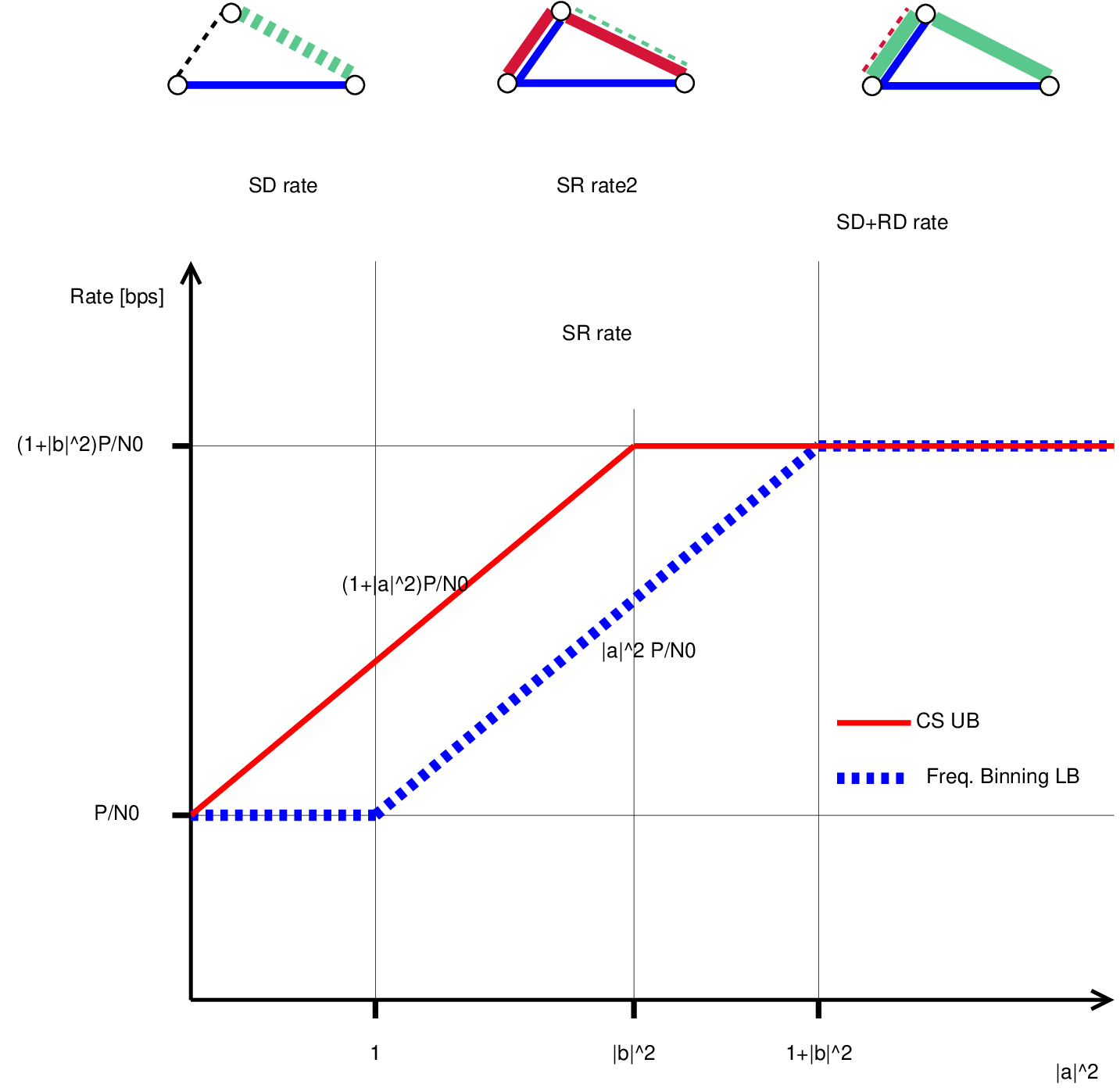
In this section, we give the correspondence between the min-cut achieving scheme in Section III, and the hypergraph model in Figure 1(b). The relaying scheme in Section III is a form of selective decode-and-forward, where the minimum amount of relayed information depends on the quality of the source-relay channel with respect to the channels and . Indeed, the amount of information forwarded by the relay is parameterized by the value of , relatively to . Three different regimes can be identified, as shown in Figure 3.
Regime : in this regime , the source-destination channel is more reliable than the source-relay channel. The source transmits directly to the destination at capacity without using the relay. This is equivalent to setting the number of bins to a single bin, , containing all messages . The achievable rate is given by the capacity of the black source-destination hyperedge.
Regime : in this regime , the source-relay channel is stronger than the source-destination channel but weaker than the cut on the multiple-access (MA) side. The source transmits at rate , by splitting into submessages sent on the blue hyperedge at rate , and sent on the red hyperedge at rate . The relay decodes and reliably forwards the bin index to the destination on the green hyperedge since . The destination will use the signals from relay and source to decode the remaining index . The number of bins is chosen such that matches the capacity of the source-destination channel, and can be handled by the source-relay and relay-destination channels. The achievable rate is given by the sum of the capacities of the red and blue hyperedges.
Regime : in this regime , the source-relay channel is better than the multiple-access cut. The source transmits at a rate equal to the capacity of the MA cut , by splitting into submessages sent on the blue hyperedge at rate , and sent on the red hyperedge at rate . The relay decodes and forwards the bin index to the destination. The destination uses the signals from source and relay to decode the remaining . The number of bins matches the capacity of the relay-destination channel, and matches the capacity of the source-destination channel. The achievable rate is given by the sum of the capacities of the green and blue hyperedges.
In those three regimes, the achievable rate is given by the hypergraph min-cut. The relationship between the rate achieved by the peaky frequency binning scheme and the min-cut on the hypergraph appears as a simple tool to derive achievable rates, and the corresponding transmission schemes, in larger wideband relaying networks.
V Conclusion
We propose a hypergaph model of the relay channel in the wideband limit, and show that its min-cut can be achieved not only in the FD-AWGN case, but also in the non-coherent multipath fading case thanks to a relaying scheme combining peaky signals and binning. In certain channel configurations, the so-obtained achievable rate also coincides with the cut-set upper-bound, and thus is equal to the capacity of the non-coherent wideband multipath fading channel.
In the remaining cases, where the rate achieved by the proposed scheme does not coincide with the cut-set upper bound, a question remains open: can the gap to the cut-set upper-bound be closed? If the capacity of the relay-destination channel was infinite, as in the SIMO channel, the cut could be achieved, and the gap to the cut-set bound could be closed. However, because of the relay power constraint and the destination noise, the relay cannot make its received signal perfectly available to the destination as in the SIMO channel. This raises the question as to whether virtual MIMO gains can actually be achieved in the wideband regime.
Acknowledgments
The work of Nadia Fawaz was supported by the French Délégation Générale pour l’Armement (DGA), by IT-MANET project under subcontract 18870740-37362-C issued by Stanford University and supported by the Defense Advanced Research Projects Agency (DARPA), and by NeTS XORS project supported by the National Science Foundation (NSF) under Grant No. CNS-0627021.
Appendix A Proof of Theorem 1: Upper bound on the Probability of Error
In this appendix, an upper bound on the probability of error of the scheme described in Section II is provided, and for all rates below (2), this upper bound is shown to vanish to when the system bandwidth grows large.
If the source transmits directly to the destination without using the relay by setting , and the probability of error at the destination decays to as grows large if
| (13) |
If , the source transmits with the help of the relay, using the scheme described in Section II with with . Assuming that message was sent by the source, the probability of error at the destination decoder can be written
| (14) |
As shown by (14), an error occurs at the destination if either or are not correctly decoded. In the sequel, we successively give upper bounds on and .
A-A Probability of error on
We first analyze the probability that the destination decoder makes an error while decoding the bin index :
| (15) |
An error on results either from an error at the relay who incorrectly decodes , which is denoted , or from an error at the destination given that the relay had correctly decoded the bin index , denoted .
Probability of error
We first analyze the probability of error at the relay . From the definition (9) of the relay decision set , it can be seen that two types of errors can happen at the relay decoder. The first type corresponds to the event . The second type of error occurs if there exists a such that , event that we call . By the union bound, the probability of error is upper-bounded by
| (16) |
The probability of errors of type is upperbounded by
| (17) |
where the second equality comes from the independence of variables . From (7), the sequence is a sequence of i.i.d. variables with mean . By the weak law of large numbers converges in probability to :
| (18) |
The probability or error can be written
| (19) |
which decays to as grows large by (18) for any and for any rate . Errors of type are not rate-limiting, on the contrary to errors of type as we will now see.
The probability of errors of type is
| (20) |
where the two last equalities are due to the fact that for all , variables are i.i.d. Using Markov’s inequality gives the upper bound
| (21) |
is a set of i.i.d. random variables. Therefore
| (22) |
recalling that is exponentially distributed with parameter and has a moment generating function for all . Using (21) and (22) in (20) yields
| (23) |
where
| (24) |
The maximum of is reached for
| (25) |
| (26) |
Finally, using (26) and (17), we can rewrite the upper bound on (16)
| (27) |
From (19) the first term in (27) vanishes to as grows large for any rate , whereas the second term vanishes to if
| (28) |
Choosing arbitrarily close to zero, and arbitrarily close to , (28) becomes
| (29) |
This bound is rather constraining since it means that message can be reliably decoded at the relay, although the relay actually forwards the bin index only.
Probability of error
We now analyze the probability of error on at the destination decoder. From the definition (10) of decision set , two types of errors can happen at the destination decoder. The first type corresponds to the event , and the second type to . By the union bound, the probability of error is upper-bounded by
| (30) |
The second term in (30) can be upper bounded using Markov’s inequality as in (21) and (22)
| (31) |
where
| (32) |
Using the maximum and (31) in (30) gives
| (33) |
As in (18) and (19) the weak law of large numbers ensures that converges in probability to , and thus that the first term in (33) decays to as grows large for any and any rate . Using the same reasoning as in (28), and choosing arbitrarily close to zero, it can be shown that the second term in (33) will vanish to when , and if
| (34) |
To summarize, in this subsection, the probability of error on , has been shown to decay to if and .
A-B Probability of error on
In this subsection, the probability that the destination decoder makes an error when decoding is analyzed, assuming that the bin index was correctly decoded: . Given , decoding is equivalent to identifying the frequency in , which contains frequencies. The upper bound on is obtained by following the same reasoning as for in Section A-A. From the definition (12) of decision set , two types of error can occur at the decoder, and the union bound gives
| (35) |
where the second inequality is due to Markov’s inequality. The weak law of large numbers ensures that the first term in (35) decays to as grows large for any , and any rate , while the second term in (35) vanishes to when , and if
| (36) |
References
- [1] T. M. Cover and A. E. Gamal, “Capacity theorems for the relay channel,” IEEE Trans. Inform. Theory, vol. 25, no. 5, pp. 572–584, Sept. 1979.
- [2] A. E. Gamal, M. Mohseni, and S. Zahedi, “Bounds on capacity and minimum energy-per-bit for awgn relay channels,” IEEE Trans. Inform. Theory, vol. 52, no. 4, pp. 1545–1561, Apr. 2006.
- [3] A. S. Avestimehr and D. N. C. Tse, “Outage capacity of the fading relay channel in the low-snr regime,” IEEE Trans. Inform. Theory, vol. 53, no. 4, pp. 1401–1415, Apr. 2007.
- [4] C. Shannon, “Communication in the presence of noise,” Proceedings of the IRE, vol. 37, no. 1, pp. 10–21, Jan. 1949.
- [5] R. S. Kennedy, Fading Dispersive Communication Channels. New York: Wiley-Interscience, 1969.
- [6] I. Telatar and D. Tse, “Capacity and mutual information of wideband multipath fading channels,” IEEE Trans. Inform. Theory, vol. 46, no. 4, pp. 1384–1400, July 2000.
- [7] L. Zheng and D. Tse, “Communication on the grassmann manifold: a geometric approach to the noncoherent multiple-antenna channel,” IEEE Trans. Inform. Theory, vol. 48, no. 2, Feb. 2002.
- [8] R. McEliece and L. Swanson, “A note on the wide-band gaussian broadcast channel,” IEEE Trans. Commun., vol. 35, no. 4, Apr. 1987.
- [9] R. G. Gallager, “A perspective on multiaccess channels,” IEEE Trans. Inform. Theory, vol. 31, no. 2, pp. 124–142, Mar. 1985.