Magnetic Faraday rotation in lossy photonic structures
Abstract
Magnetic Faraday rotation is widely used in optics and MW. In uniform magneto-optical materials, this effect is very weak. One way to enhance it is to incorporate the magnetic material into a high-Q optical resonator. One problem with magneto-optical resonators is that along with Faraday rotation, the absorption and linear birefringence can also increase dramatically, compromising the device performance. Another problem is strong ellipticity of the output light. We discuss how the above problems can be addressed in the cases of optical microcavities and a slow wave resonators. We show that a slow wave resonator has a fundamental advantage when it comes to Faraday rotation enhancement in lossy magnetic materials.
1 Introduction
Magnetic materials play a crucial role in optics. They are essential in numerous non-reciprocal devices such as optical isolators, circulators, phase shifters, etc. A well-known example of nonreciprocal effects is magnetic Faraday rotation related to nonreciprocal circular birefringence. Nonreciprocal effects only occur in magnetically ordered materials, such as ferromagnets and ferrites, or in the presence of bias magnetic field [1, 2]. At optical frequencies, all nonreciprocal effects are very weak, and can be further obscured by absorption, linear and/or form birefringence, etc. A way to enhance a weak Faraday rotation is to incorporate the magneto-optical material into a resonator, which can be a complex nanophotonic structure with feature sizes comparable to the light wavelength [3, 4, 5, 6, 7, 8, 9, 10]. An intuitive explanation for the resonance enlacement invokes a simple idea that in a high-Q optical resonator filled with magneto-optical material, each individual photon resides much longer compared to the same piece of magnetic material taken out of the resonator. Since the nonreciprocal circular birefringence is independent of the direction of light propagation, one can assume that the magnitude of Faraday rotation is proportional to the photon residence time in the magnetic material. With certain reservations, the above assumption does provide a hand-waving explanation of the resonance enhancement of magnetic Faraday rotation, as well as many other light-matter interactions.
Resonance conditions can indeed result in a significant enhancement of nonreciprocal effects, which in our case is a desirable outcome. On the other hand, the same resonance conditions can also enhance absorption and linear birefringence in the same magnetic material, which would be undesirable. Indeed, linear and/or form birefringence, if present, can significantly suppress the Faraday rotation, or any other manifestation of nonreciprocal circular birefringence. Even more damaging can be absorption. In uniform magneto-optical materials, the absorption contributes to the ellipticity of propagating electromagnetic wave by causing circular dichroism. In low-loss uniform magnetic materials those effects are insignificant. Under the resonance condition, though, the role of absorption can change dramatically. Firstly, the enhanced absorption reduces the intensity of light transmitted through the optical resonator. Secondly, even moderate absorption can lower the Q-factor of the resonance by several orders of magnitude and, thereby, significantly compromise its performance as Faraday rotation enhancer. Finally, enhanced absorption, along with spatial nonuniformity, contributes to deviation of the transmitted light polarization from linear, making it difficult to measure the amount of Faraday rotation.
We explore the idea of composite magneto-photonic structures having enhanced nonreciprocal characteristics associated with magnetism but, at the same time, significantly reducing the light absorption. In other words, we want to enhance the useful characteristics of a particular magnetic material, while drastically reducing its contribution to the energy dissipation. The possibility of appreciable enhancement of Faraday rotation or other nonreciprocal effects is particularly important at infrared and optical frequencies, where all light-matter interactions are very weak. In those cases, the use of photonic structures instead of uniform magnetic materials can also dramatically reduce the size of the respective optical components, without compromising their performance.
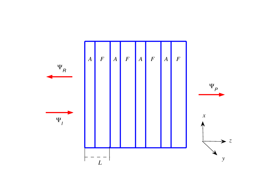
We also compare two qualitatively different approaches to resonance enhancement of light-matter interactions. The first one is based on a magnetic microcavity sandwiched between a pair of Bragg reflectors, as shown in Fig. 1. The second approach is based on a slow wave resonance in a magnetic photonic crystal, an example of which is shown in Fig. 2. In either case, one can simultaneously enhance the useful characteristics of a particular magnetic material, while reducing its contribution to the energy dissipation. Yet, the above two approaches are qualitatively different, and which one is preferable depends on specific circumstances. For instance, if the absorption of light by the magnetic material is an issue, the slow wave resonance is definitely preferable. Otherwise, if the light absorption is insignificant and the only goal is to enhance the magnetic Faraday rotation, then the microcavity resonance can be a better choice.
2 Absorption suppression in composite structures
How is it possible to enhance Faraday rotation produced by the lossy magnetic component of composite structure, while reducing the losses caused by the same magnetic material? Following [14], we can use the fact that the absorption and the useful functionality of the particular magnetic material are related to different components of its permittivity and/or permeability tensors and . Specifically, the absorption is determined by the anti-Hermitian parts and the permittivity and permeability tensors
| (1) |
while the nonreciprocal circular birefringence responsible for the Faraday rotation is determined by the Hermitian skew-symmetric parts of the respective tensors
| (2) |
where denotes Hermitian conjugate. The relations (1) and (2) suggest that the rate of energy absorption by the lossy magnetic material can be functionally different from its useful functionality (nonreciprocal circular birefringence in our case). Such a difference allows us to adjust the physical and geometric characteristics of the periodic structure so that the electromagnetic field distribution inside the photonic structure suppresses the energy dissipation by the lossy magnetic component, while even enhancing its useful functionality. The way to address the problem essentially depends on the following factors.
- 1.
The physical mechanism of Faraday rotation.
- 2.
The dominant physical mechanism of absorption. For instance, energy dissipation caused by electric conductivity requires a different approach, compared to the situation where the losses are associated with the dynamics of magnetic domains, or some other physical mechanisms. In each individual case, the structure of the anti-Hermitian part (1) of the permittivity and/or permeability tensors can be different, and so can be the optimal configuration of the composite material.
- 3.
The frequency range of interest. A given photonic structure can dramatically enhance Faraday rotation at some frequencies, while sharply reducing it at different frequencies. The same is true with absorption, which can be either suppressed, or enhanced, depending on the frequency range.
Since our goal is to enhance Faraday rotation while reducing absorption, the same photonic structure can be either effective or counterproductive, depending on the frequency range and the dominant physical mechanism of electromagnetic energy dissipation. Fortunately, in some important cases, the photonic structure can be engineered in such a way that it only enhances the useful light-matter interaction, while limiting or even suppressing the absorption. Usually, it can be done if the useful functionality and the absorption are associated with different components of electromagnetic field. An impressive example of the kind is considered in [14], where a simple layered structure provides significant enhancement of Faraday rotation produced by a lossy magnetic component, while dramatically reducing absorption caused by the same magneto-optical material.
Under what circumstances can we not only suppress the absorption but also have the size of the periodic composite structure much smaller than that of the uniform (magnetic) slab with similar performance? When considering this question we should keep in mind that within the framework of the photonic approach the characteristic length of the the structural components is always comparable to that of the electromagnetic wavelength in the medium. Therefore, for a given frequency range and for a given set of the constitutive materials, we cannot significantly change the length . Nor can we substantially reduce the number of unit cells of the periodic structure without loosing all the effects of coherent interference. All we can achieve by adjusting the configuration of the periodic array comprising as few as several periods is to suppress the losses and/or to enhance the Faraday rotation. The real question is: what is the thickness of the uniform slab producing Faraday rotation comparable to that of the optimized photonic structure? Indeed, if such a uniform slab turns out to be much thicker than the layered structure, then we can claim that not only the periodic array dramatically reduces the losses, but it also has much smaller dimensions. The latter is only possible if the thickness of the uniform slab with desired functionality is much greater than the electromagnetic wavelength in the medium. Otherwise, all we can achieve by introducing periodic inhomogeniety would be a reduction of losses. At optical frequencies, due to the weakness of light-matter interactions, the thickness of the uniform slab producing significant Faraday rotation is indeed much greater than the light wavelength. Therefore, in optics we can simultaneously suppress the losses, while reducing the size of the nonreciprocal optical device.
If the resonance Q-factor is high enough, the acquired ellipticity becomes so significant that the very term ”Faraday rotation” becomes irrelevant. Indeed, one cannot assign a meaningful rotation angle to a wave with nearly circular polarization. The above circumstance, though, does not diminish the practical importance of the nonreciprocal effect, which now reduces to the conversion of linear polarization of the incident wave to nearly circular polarization of transmitted and/or reflected waves.
3 Notations, definitions, and physical assumptions
3.1 Transverse electromagnetic waves in stratified media
Our analysis is based on the time-harmonic Maxwell equations
| (3) |
where the second rank tensors and are coordinate dependent. In a stratified medium
where the Cartesian coordinate is normal to the layers. We also assume that the dielectric permittivity and magnetic permeability tensors in each layer has the following form
| (4) |
in which case the layered structure support transverse electromagnetic waves with
| (5) |
propagating along the direction. The Maxwell equations (3) in this case reduce to the following system of four ordinary differential equations
| (6) |
where
| (7) |
and
| (8) |
The matrix is referred to as the (reduced) Maxwell operator.
Solutions for the reduced time-harmonic Maxwell equation (6) can be presented in the following form
| (9) |
where the matrix is the transfer matrix. The transfer matrix (9) uniquely relates the values of electromagnetic field (7) at any two points and of the stratified medium.
In a uniform medium, the Maxwell operator in (8) is independent of . In this case, the transfer matrix can be explicitly expressed in terms of the respective Maxwell operator
| (10) |
In particular, the transfer matrix of an individual uniform layer is
| (11) |
where is the thickness of the -th layer.
The transfer matrix of an arbitrary stack of layers is a sequential product of the transfer matrices of the constituent layers
| (12) |
3.2 Permittivity and permeability tensors of the layers
We assume that the permittivity and permeability tensors of individual layers have the following form
| (13) |
where is responsible for nonreciprocal circular birefringence and describes linear birefringence. In a lossless medium, the physical quantities , , and are real. If the direction of magnetization is changed for the opposite, the parameters also changes its sign and so will the sense of Faraday rotation [1, 2]. The absorption, is accounted for by allowing , , and to be complex.
Substitution of (13) into (8) yields the following expression for the Maxwell operator
| (14) |
The respective four eigenvectors are
| (15) |
where
| (16) |
| (17) |
Compared to [6], we use slightly different notations.
The explicit expression for the transfer matrix of a single uniform layer of thickness is
| (18) |
where
| (19) |
and
The eigenvectors (15) correspond to elliptically polarized states. There are two important particular cases corresponding to linearly and circularly polarized eigenmodes, respectively.
3.2.1 Non-magnetic medium with linear birefringence
In the case of a non-magnetic medium
| (20) |
The respective eigenmodes are linearly polarized
| (21) |
where
3.2.2 Magnetic medium with circular birefringence
Another important limiting case corresponds to a uniaxial magnetic medium with
| (22) |
The respective eigenmodes are circularly polarized
| (23) |
where
3.3 Numerical values of material tensors
Our objectives include two distinct problems associated with Faraday rotation enhancement.
One problem can be caused by the presence of linear birefringence described by the parameter in (13). Linear birefringence competes with circular birefringence . At optical frequencies, the former can easily prevail and virtually annihilate any manifestations of nonreciprocal circular birefringence. If linear birefringence occurs in magnetic F layers in Fig. 2, it can be offset by linear birefringence in the alternating dielectric A layers. Similarly, in the case of a magnetic resonance cavity in Fig. 1, the destructive effect of the linear birefringence in the magnetic D layer can be offset by linear birefringence in layers constituting the Bragg reflectors. In either case, the cancellation of linear birefringence of the magnetic layers only takes place at one particular frequency. Therefore, the layered structure should be designed so that this particular frequency coincides with the operational resonance frequency of the composite structure. The detailed discussion on the effect of linear birefringence and ways to deal with it will be presented elsewhere.
In the rest of the paper we will focus on the problem associated with absorption. This problem is unrelated to the presence or absence of linear birefringence and, therefore, can be handled separately. For this reason, in our numerical simulation we can set and use the following expressions for the dielectric permittivity tenors of the magnetic F-layers and dielectric A-layers in Fig. 2
| (24) |
| (25) |
where , , and are real. Parameter describes absorption of the magnetic material.
In the case of photonic cavity in Fig. 1 we use similar material parameters. The permittivity tensor of the magnetic D-layer is the same as that of the magnetic F-layers in Fig. 2
| (26) |
is defined in (24). The permittivity tensors of the alternating dielectric layers A and B constituting the Bragg reflectors in Fig. 1 are chosen as follows
| (27) |
In either case, only the magnetic layers F or D are responsible for absorption, which is a realistic assumption.
In the case of periodic stack in Fig. 2 we use the following numerical values of the diagonal components of the permittivity tensors
| (28) |
Similar values are used in the case of photonic microcavity in Fig. 1
The numerical values of the gyrotropic parameter , as well as the absorption coefficient of the magnetic layers F and D, remain variable. We also tried different layer thicknesses ,,, , and . But in this paper we only include the results corresponding to the following numerical values
| (29) |
where is the length of a unit cell of the periodic array
The thickness of the defect layer in Fig. 1 is chosen so that the frequency of the defect mode falls in the middle of the lowest photonic band gap of Bragg reflectors.
3.4 Scattering problem for magnetic layered structure
In all cases, the incident wave propagates along the direction normal to the layers. Unless otherwise explicitly stated, the incident wave polarization is linear with . Due to the nonreciprocal circular birefringence of the magnetic material, the transmitted and reflected waves and will be elliptically polarized with the ellipse axes being at an angle with the direction.
The transmitted and reflected waves, as well the electromagnetic field distribution inside the layered structure, are found using the transfer matrix approach. Let us assume that the left-hand and the right-hand boundaries of a layered array are located at and , respectively. According to (9) and (12), the incident, transmitted, and reflected waves are related as follows
| (30) |
Knowing the incident wave and the transfer matrix of the entire layered structure and assuming, we can solve the system (30) of four linear equations and, thereby, find the reflected and transmitted waves. Similarly, using the relation (9), we can also find the field distribution inside the layered structure.
The transmission and reflection coefficients of the slab (either uniform, or layered) are defined as follows
| (31) |
where , , and are the Poynting vectors of the incident, transmitted, and reflected waves, respectively. The slab absorption is
| (32) |
If the incident wave polarization is linear, the coefficients , , and are independent of the orientation of vector in the plane, because for now, we neglect the linear birefringence . Due to nonreciprocal circular birefringence, the polarization of the transmitted and reflected waves will always be elliptic.
By contrast, if the incident wave polarization is circular, the coefficients , , and depend on the sense of circular polarization. The polarization of the transmitted and reflected waves in this case will be circular with the same sense of rotation as that of the incident wave.
The effect of nonreciprocal circular birefringence on transmitted wave can be quantified by the following expression
| (33) |
where and respectively correspond to the wave transmitted through the original periodic structure and through the same structure but with the opposite sign of circular birefringence parameter . If the incident wave polarization is linear with , the vector-column (33) has the following simple structure
implying that the component of the transmitted wave has ”purely” nonreciprocal origin and, therefore, can used to characterize the magnitude of nonreciprocal circular birefringence on transmitted wave. Indeed, in the absence of magnetism, the parameter in (13), (24), and 26) vanishes and the transmitted wave is linearly polarized with . The above statement follows directly from symmetry consideration and remains valid even in the presence of linear birefringence in (13). Further in this paper will use the ratio
| (34) |
to characterize the effect circular birefringence on transmitted wave.
Generally, the transmitted wave polarization in the situation in Figs. 2 and 1 is elliptical, rather than linear. Therefore, the quantity in (34) is not literally the sine of the Faraday rotation angle. Let us elaborate on this point. The electromagnetic eigenmodes of the layered structures in Figs. 2 and 1 with permittivity tensors given in (24) through (27) are all circularly polarized. This implies that if the polarization of the incident wave is circular, the transmitted and reflected waves will also be circularly polarized. On the other hand, due to the nonreciprocal (magnetic) effects, the transmission/reflection coefficients for the right-hand circular polarization are different from those for the left-hand circular polarization. This is true regardless of the presence or absence of absorption. Consider now a linearly polarized incident wave. It can be viewed as a superposition of two circularly polarized waves with equal amplitudes. Since the transmission/reflection coefficients for the right-hand and left-hand circular polarizations are different, the transmitted and reflected waves will be elliptically polarized. Such an ellipticity develops both in the case of a uniform slab and in the case of a layered stack, periodic or aperiodic, with or without absorption. Note, though, that at optical frequencies, the dominant contribution to ellipticity of the wave transmitted through a uniform slab is usually determined by absorption, which is largely responsible for circular dichroism. Without absorption, the ellipticity of the wave transmitted through a uniform magnetic slab would be negligible. This might not be the case for the layered structures in Figs. 2 and 1 at frequencies of the respective transmission resonances. In these cases, the ellipticity of transmitted and reflected waves can be significant even in the absence of absorption. Moreover, if the Q-factor of the respective resonance is high enough, the transmitted wave polarization becomes very close to circular and, therefore, cannot be assigned any meaningful angle of rotation. The numerical examples of the next section illustrate the above statements.
To avoid confusion, note that a linear polarized wave propagating in a uniform, lossless, unbounded, magnetic medium (24) will not develop any ellipticity. Instead, it will display a pure Faraday rotation. But the slab boundaries and the layer interfaces will produce some ellipticity even in the case of lossless magnetic material. The absorption provides an additional contribution to the ellipticity of transmitted and reflected waves. The latter contribution is referred to as circular dichroism.
For simplicity, in further consideration we will often refer to the quantity in (34) as the amount of (nonreciprocal) Faraday rotation, although, due to the ellipticity, it is not exactly the sine of the Faraday rotation angle.
4 Resonance enhancement of magnetic Faraday rotation
4.1 Cavity resonance: Lossless case
Let us start with the resonance enhancement based on microcavity. The magnetic layer D in Fig. 1 is sandwiched between two identical periodic stacks playing the role of distributed Bragg reflectors. The D-layer is also referred to as a defect layer, because without it, the layered structure in Fig. 1 would be perfectly periodic. The thickness of the defect layer is chosen so that the microcavity develops a single resonance mode with the frequency lying in the middle of the lowest photonic band gap of the adjacent periodic stacks. This resonance mode is nearly localized in the vicinity of the magnetic D-layer.
A typical transmission spectrum of such a layered structure in the absence of absorption is shown in Fig. 3. The stack transmission develops a sharp peak at the defect mode frequency. The respective transmission resonance is accompanied by a dramatic increase in field amplitude in the vicinity of the magnetic D-layer. The large field amplitude implies the enhancement of magnetic Faraday rotation produced by the D-layer, as clearly seen in Fig. 4.
If the Q-factor of the microcavity exceeds certain value and/or if the circular birefringence of the magnetic material of the D-layer is strong enough, the resonance frequency of the defect mode splits into two, as shown in Fig. 4(c) and (d). Each of the two resonances is associated with left or right circular polarization. The transmitted light will also display nearly perfect circular polarization with the opposite sense of rotation for the twin resonances. Formally, the above nonreciprocal effect cannot be classified as Faraday rotation, but it does not diminish its practical value.
4.2 Slow wave resonance: Lossless case
The second approach to Faraday rotation enhancement is based on the transmission band edge resonance in periodic stacks of magnetic layers alternating with some other dielectric layers, as shown in Fig. 2. A typical transmission spectrum of such a layered structure is shown in Fig. 7. The sharp peaks in transmission bands correspond to transmission band edge resonances, also known as Fabry-Perot resonances. The resonance frequencies are located close to a photonic band edge, where the group velocity of the respective Bloch eigenmodes is very low. This is why the transmission band edge resonances are referred to as slow wave resonances. All resonance frequencies are located in transmission bands – not in photonic band gaps, as in the case of a localized defect mode. The resonance field distribution inside the periodic stack is close to a standing wave composed of a pair of Bloch modes with equal and opposite group velocities and nearly equal large amplitudes
| (35) |
The left-hand and right-hand photonic crystal boundaries coincide with the standing wave nodes, where the forward and backward Bloch components interfere destructively to meet the boundary conditions. The most powerful slow wave resonance corresponds to the transmission peak closest to the respective photonic band edge, where the wave group velocity is lowest. At resonance, the energy density distribution inside the periodic structure is typical of a standing wave
| (36) |
where is the intensity of the incident light, is the total number of unit cells (double layers) in the periodic stack in Fig. 2.
Similarly to the case of magnetic cavity resonance, the large field amplitude implies the enhancement of magnetic Faraday rotation produced by magnetic F-layers, as demonstrated in Fig. 9. Again, if the Q-factor of the slow wave resonance exceeds certain value and/or if the circular birefringence of the magnetic material of the F-layers is strong enough, each resonance frequency splits into two, as shown in Fig. 10. Each of the two twin resonances is associated with left or right circular polarization. To demonstrate it, let us compare the transmission dispersion in Fig. 10, where the incident light polarization is linear, to the transmission dispersion in Figs. 11 and 12, where the incident wave is circularly polarized. One can see that the case in Fig. 10 of linearly polarized incident light reduces to a superposition of the cases in Figs. 11 and 12 of two circularly polarized incident waves with opposite sense of rotation.
4.3 The role of absorption
In the absence of absorption, the practical difference between cavity resonance and slow wave resonance is not that obvious. But if the magnetic material displays an appreciable absorption, the slow wave resonator is definitely preferable. The physical reason for this is as follows.
In the case of a slow wave resonance, the reduction of the transmitted wave energy is mainly associated with absorption. Indeed, although some fraction of the incident light energy is reflected at the left-hand interface of the periodic stack in Fig. 2, this fraction remains limited even in the case of strong absorption, as seen in Fig. 8(b). So, the main source of the energy losses in a slow wave resonator is absorption, which is a natural side effect of the Faraday rotation enhancement (some important reservations can be found in [14]).
In the case of magnetic cavity resonance, the situation is fundamentally different. In this case, the energy losses associated with absorption cannot be much different from those of slow wave resonator, provided that both arrays display comparable enhancement of Faraday rotation. What is fundamentally different is the reflectivity. An inherent problem with any (localized) defect mode is that any significant absorption in defect layer makes it inaccessible. Indeed, if the D-layer in Fig. 1 displays an appreciable absorption, the entire structure becomes highly reflective. As a consequence, a major portion of the incident light energy is reflected from the stack surface and never even reaches the magnetic D-layer. Such a behavior is illustrated in Fig. 6, where we can see that as soon as the absorption coefficient exceeds certain value, further increase in leads to high reflectivity of the layered structure. In the process, the total absorption reduces, as seen in Fig. 5, but the reason for this reduction is that the light simply cannot reach the magnetic layer. There is no Faraday rotation enhancement in this case.
Acknowledgments: Effort of A. Figotin and I. Vitebskiy is sponsored by the Air Force Office of Scientific Research, Air Force Materials Command, USAF, under grant number FA9550-04-1-0359.
References
- [1] L. D. Landau, E. M. Lifshitz, L. P. Pitaevskii. Electrodynamics of continuous media. (Pergamon, N.Y. 1984).
- [2] A. G. Gurevich and G. A. Melkov. Magnetization Oscillations and Waves. (CRC Press, N.Y. 1996).
- [3] M. Inoue, et all. Magnetophotonic crystals (Topical Review). J. Phys. D: Appl. Phys. 39, R151–R161 (2006).
- [4] I. Lyubchanskii1, N. Dadoenkova1, M. Lyubchanskii1, E. Shapovalov, and T. Rasing. Magnetic photonic crystals. J. Phys. D: Appl. Phys. 36, R277–R287 (2003)
- [5] M. Inoue, K. Arai, T. Fuji, and M. Abe. One-dimensional magnetophotonic crystals. J. Appl. Phys. 85, 5768 (1999).
- [6] M. Levy and A. A. Jalali. Band structure and Bloch states in birefringent onedimensional magnetophotonic crystals: an analytical approach. J. Opt. Soc. Am. B, 24, 1603-1609 (2007).
- [7] M. Levy and R. Li. Polarization rotation enhancement and scattering mechanisms in waveguide magnetophotonic crystals. Appl. Phys. Lett. 89, 121,113 (2006)..
- [8] S. Khartsev and A. Grishin. High performance magneto-optical photonic crystals. J. Appl. Phys. 101, 053,906 (2007).
- [9] S. Kahl and A. Grishin. Enhanced Faraday rotation in all-garnet magneto-optical photonic crystal. Appl. Phys. Lett. 84, 1438 (2004).
- [10] S. Erokhin, A. Vinogradov, A. Granovsky, and M. Inoue. Field Distribution of a Light Wave near a Magnetic Defect in One-Dimensional Photonic Crystals. Physics of the Solid State, 49, 497 (2007).
- [11] Vol. 49
- [12] A. Figotin, and I. Vitebsky. Nonreciprocal magnetic photonic crystals. Phys. Rev. E63, 066609 (2001).
- [13] A. Figotin, and I. Vitebskiy. Electromagnetic unidirectionality in magnetic photonic crystals. Phys. Rev. B67, 165210 (2003)
- [14] A. Figotin and I. Vitebskiy. Absorption suppression in photonic crystals. Phys. Rev. B77, 104421 (2008)