Quantum Mechanical Simulations of Nanoindentation of Al Thin Film
Abstract
QCDFT is a multiscale modeling approach that can simulate multi-million atoms effectively via density functional theory (DFT). The method is based on the framework of quasicontinuum (QC) approach with DFT as its sole energetics formulation. The local QC energy is calculated by DFT with Cauchy-Born hypothesis and the nonlocal QC energy is determined by a self-consistent embedding approach, which couples nonlocal QC atoms to the vertices of the finite-elements at the local QC region. The QCDFT method is applied to a nanoindentation study of an Al thin film in the presence and absence of Mg impurities. The results show that the randomly distributed Mg impurities can significantly increase the ideal and yield strength of the Al thin film.
Keywords:
Quantum mechanics/molecular mechanics , nanoindentation , First-Principles Electron Structure Theory , embedding theory , multiscalePACS
71.15.Mb , 62.20.Mk , 71.15.Dx1 Introduction
The ability to perform quantum mechanical simulations of materials properties over length scales that are relevant to experiments represents a grand challenge in computational materials science. If one could treat multi-millions or billions of electrons effectively at micron scales, such first-principle quantum simulations could revolutionize materials research and pave the way to the computational design of advanced materials.
In this paper, we propose a multiscale approach that is based entirely on density functional theory (DFT) and allows quantum simulations at micron scale and beyond. The method, termed QCDFT(Peng et al., 2008), combines the coarse graining idea of the quasicontinuum (QC) approach and the coupling strategy of the quantum mechanics/molecular mechanics (QM/MM) method, and represents a major advance in the quantum simulation of materials properties. It should be stated at the outset that QCDFT is not a brute-force electronic structure method, but rather a multiscale approach that can treat large systems - effectively up to billions of electrons. Therefore, some of the electronic degrees of freedom are reduced to continuum degrees of freedom in QCDFT. On the other hand, although QCDFT utilizes the idea of QM/MM coupling, it does not involve any classical/empirical potentials (or force fields) in the formulation - the energy calculation of QCDFT is entirely based on DFT. This is an important feature and advantage of QCDFT, which qualifies it as a bona fide quantum mechanical simulation method.
Since QCDFT is formulated within the framework of the QC method, we shall give a brief introduction to QC in Sec. 2.1 to set up the stage of QCDFT. In Sec. 2.2, we briefly explain the local QC calculations. In Sec. 2.3, we introduce a DFT-based QM/MM approach that can treat the nonlocal QC region accurately and efficiently. In Sec. 3, we apply QCDFT to the study of nanoindentation of an Al thin film in the presence and absence of Mg impurities. We present the nanoindentation results in Sec. 4 and finally our conclusions in Sec. 5.
2 QCDFT Methodology
2.1 Quasicontinuum Method
The goal of the QC method is to model an atomistic system without explicitly treating every atom in the problem (Tadmor et al., 1996; Shenoy et al., 1999). This is achieved by replacing the full set of atoms with a small subset of “representative atoms” or repatoms () that approximate the total energy through appropriate weighting. The energies of individual repatoms are computed in two different ways depending on the deformation in their immediate vicinity. Atoms experiencing large variations in the deformation gradient on an atomic scale are computed in the same way as in a standard atomistic method. In QC these atoms are called nonlocal atoms. In contrast, the energy of atoms experiencing a smooth deformation field on the atomic scale is computed based on the deformation gradient in their vicinity as befitting a continuum model. These atoms are called local atoms because their energy is based only on the deformation gradient at the point where it is computed. In a classical system where the energy is calculated based on classical/empirical interatomic potentials, the total energy can be written
| (1) |
The total energy has been divided into two parts: an atomistic region of nonlocal atoms and a continuum region of local atoms (). The calculation in the nonlocal region is identical to that in atomistic methods with the energy of the atom depending on the coordinates of the surrounding repatoms. Rather than depending on the positions of neighboring atoms, the energy of a local repatom depends on the deformation gradients characterizing the finite strain around its position.
2.2 Local QC calculation with DFT
In the local QC region, a finite element mesh is constructed with each repatom on the vertices of surrounding finite elements. The energy and force of each local repatom can be obtained from the strain energy density and the stress tensor of the finite elements that share the same repatom. More specifically, according to the Cauchy-Born rule, the deformation gradient is the same for a given finite element, therefore the local energy density and the stress tensor for each finite element can be calculated as a perfect infinite crystal undergoing a uniform deformation specified by . In other words, one could perform a DFT-based energy/stress calculation for an infinite crystal by using periodic boundary conditions with the primitive lattice vectors of the deformed crystal, given by
| (2) |
Here are the primitive lattice vectors of the perfect undeformed crystal and is the volume of the primitive unit cell. The deformed crystal can be derived from the perfect crystal via the deformation gradient as shown in Fig. 1

For the deformation gradient associated with the th element, a periodic DFT calculation can be performed to determine the strain energy per unit cell . The Cauchy stress tensor can be defined as follows:
| (3) |
with being the volume of the deformed unit cell and denoting the component of the deformed lattice vector in Cartesian coordinate .
Once the strain energy is determined, the energy contribution of the th local repatom is given as
| (4) |
where is the total number of finite elements shared by the th repatom, and is the weight associated with the th finite element for the th local repatom. The force on the th local repatom is defined as the gradient of the total energy with respect to its coordinate . In practice, the nodal force on each finite element is calculated from the stress tensor of the finite element by using the Principle of Virtual Work (Zienkiewicz and Taylor, 2000). The force on the repatom is then obtained by summing the nodal force contributions from each surrounding finite elements.
2.3 Nonlocal QC calculation with DFT
The nonlocal QC is modeled at the atomistic level with a QM/MM approach. In a typical QM/MM calculation, the system is partitioned into two domains: a QM region and an MM region. In QCDFT, the QM atoms refer to the nonlocal repatoms and the MM atoms refer to the buffer atoms which are the combination of both dummy atoms and local repatoms in QC terminology. The so-called dummy atoms are in the local region and are not independent degrees of freedom, but rather slaves to the local repatoms. In other words, the position of a dummy atom is determined by the finite element interpolation from the relevant local repatom positions(Tadmor et al., 1996; Shenoy et al., 1999). The dummy atoms provide the appropriate boundary conditions for nonlocal DFT calculation while the energy of the dummy atoms is still treated with the Cauchy-Born rule, consistent with their status. The self-consistent embedding theory (Choly et al., 2005; Zhang and Lu, 2007; Zhang et al., 2008) is employed for the QM/MM calculations. More specifically, both the energy of the nonlocal atoms and the interaction energy between the nonlocal atoms and the buffer atoms are calculated by DFT. To simply the notation, we denote the nonlocal region as region I, and the buffer region as region II, as shown in Fig. 2. Typically, the buffer region consists of several atomic layers surrounding the nonlocal region. We associate each buffer atom in region II with a valence electron density () and a pseudopotential; both of them are constructed a priori and remain fixed during a QM/MM simulation. (Zhang and Lu, 2007) The nonlocal energy as defined in Eq. (1) can be expressed as
| (5) |
Here and denote atomic coordinates in region I and II respectively. The charge density of region I, , is the degree of freedom and is determined self-consistently by minimizing the nonlocal energy functional. The charge density of region II, , is defined as the superposition of atomic-centered charge densities via , which only changes upon the relaxation of region II ions. is the interaction energy between regions I and II computed by orbital-free DFT (OFDFT) (Wang and Carter, 2000; Wang and Teter, 1992).

A basic ansatz of the nonlocal energy functional (Eq. (5)) is that must be confined within a finite volume () that is necessarily larger than region I but much smaller than the entire QM/MM region. In addition, since some terms in the formulation of Eq. (5) could be more efficiently computed in reciprocal space (Zhang and Lu, 2007), we also introduce a volume over which the periodic boundary conditions are applied. The periodic box should be large enough to avoid the coupling errors induced by the implementation of periodic boundary condition (Zhang and Lu, 2007).
The interaction energy, , formulated by OFDFT is defined as following:
| (6) |
where and . In addition to its computational efficiency, OFDFT allows Eq. (9) to be evaluated over rather than over the entire QM/MM system as Eq. (9) appears to suggest (Choly et al., 2005; Zhang and Lu, 2007). This significant computational saving is due to the cancellation in evaluating the first and second term of Eq. (9), and it is rendered by the orbital-free nature of OFDFT and the localization of . A single-particle embedding potential can be defined as a functional derivative of the interaction energy with respect to
| (7) |
which represents the effective potential that region I electrons feel due to the presence of region II; (Choly et al., 2005; Zhang and Lu, 2007) it is through that the QM/MM coupling is achieved quantum mechanically at the level of OFDFT. The embedding potential provides rigorous boundary conditions for and is updated self-consistently during the minimization of the nonlocal energy functional.
Since is a key quantity for the accurate calculation of the interaction energy and the embedding potential, it is crucial to construct an appropriate representation of . In fact, the construction of an appropriate charge density distribution in region II represents a common challenge to many QM/MM methods. (Lin and Truhlar, 2007) In this paper, we represent as a superposition of spherical atomic-like charge densities centered on each ions in region II, which is a good approximation for metallic systems. Ideally, the constructed should reproduce the bulk (or solid) charge density obtained by a DFT calculation of the perfect lattice. That is to say, one needs to determine by minimizing the function
| (8) |
with . Here represents the volume of the unit cell, and is the solid charge density obtained by a periodic DFT calculation for the perfect reference system. The summation of includes all the ions which have contribution to the charge density in the unit cell.

In this paper, we employ the parameterized multiple Slater-type orbitals (MSTO) (Clementi and Roetti, 1974) for the expansion of . With MSTO, the atomic wave function of many-electronis is the superposition of all relevant atomic orbitals: , where is the weight of orbital in the expansion and the th atomic orbital can be written as
| (9) |
where , , are the principal, angular momentum and magnetic quantum number of the orbital. is spherical harmonic function and is related to the effective charge of the ion. is a normalization constant and is expressed as . With this expansion, the atomic-centered charge density can be calculated as
| (10) |
The parameters and are determined by minimizing Eq. (8) with the constraint of preserving the correct number of valence electrons. In Fig. 3, we present the solid charge density determined from and from the periodic DFT calculation for a perfect Al lattice. It can be seen that the constructed reproduces very well the solid charge density calculated by DFT calculations for the same perfect lattice.
3 Computational details
3.1 Model setup
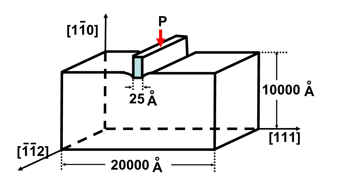
The present QCDFT approach is applied to nanoindentation of an Al thin film resting on a rigid substrate with a rigid knife-like indenter. The QCDFT method is appropriate for the problem because it allows the modeling of system dimensions on the order of microns and thus minimizes the possibility of contaminating the results by the boundary conditions arising from small model sizes typically used in MD simulations. The reason we chose this particular system is because there exists a good kinetic energy functional and an excellent EAM potential (Ercolessi and Adams, 1994) for Al. In this paper, we have rescaled the “force-matching" EAM potential of Al (Ercolessi and Adams, 1994) so that it matches precisely the DFT value of the lattice constant and bulk modulus of Al (Peng et al., 2008).
The crystallographic orientation of the system is displayed in Fig. 4. The size of the entire system is 2 m 1 m 4.9385 Å along the [111] (x direction), the [10] (y direction), and the [] (z direction), respectively. The system is periodic in the z-dimension and has the Dirichlet boundary conditions in the other two directions. The entire system contains over 60 million Al atoms - a size that is well beyond the reach of any full-blown quantum mechanical calculation. The unloaded system is a perfect single crystal similar to the experimental situation. The film is oriented so that the preferred slip system is parallel to the indentation direction to facilitate dislocation nucleation. The indenter is a rigid flat punch of width 25 Å. We assume the perfect-stick boundary condition for the indenter so that the Al atoms in contact with it are not allowed to slip. The knife-like geometry of the indenter is dictated by the pseudo two-dimensional (2D) nature of the QC model adopted. Three-dimensional QC models do exist and can be implemented in QCDFT (Knap and Ortiz, 2003; Hayes et al., 2005; Hayes et al., 2006). We chose to work with the pseudo-2D model in this example for its simplicity. The prefix pseudo is meant to emphasize that although the analysis is carried out in a 2D coordinate system, the out-of-plane displacements are allowed and all atomistic calculations are three-dimensional. Within this setting only dislocations with line directions perpendicular to the xy plane can be nucleated.
The simulation is performed quasistatically with a displacement control where the indentation depth () is increased by 0.1 Å at each loading step. Because DFT calculations are much more expensive than EAM, we use EAM-based QC(Tadmor et al., 1999b) to relax the system for most of the loading steps first. At Å, the corresponding EAM configurations are further relaxed by QCDFT. The QCDFT loadings are carried out after Å starting from the full relaxed EAM-QC configuration of previous loading step, until the onset of the plasticity occurs at Å. Such a simulation strategy is justified based on two considerations: (1) an earlier nanoindentation study of the same Al surface found that the onset of plasticity occurred at a smaller load with EAM-based local QC calculations comparing to OFDFT-based local QC calculations (Hayes et al., 2005). The result was obtained by a local elastic stability analysis with EAM and OFDFT calculations of energetics and stress. This suggests that we will not miss the onset of plasticity with the present loading procedure by performing EAM-QC relaxations preceding QCDFT. (2) Before the onset of plasticity, the load-displacement response is essentially linear with the slope determined by the elastic properties of the material. In other words, only two QCDFT calculations are required to obtain the linear part of the loading curve.

We also study the effect of Mg impurities on the ideal strength and incipient plasticity of the Al thin film. In the calculations, five Mg impurities are introduced randomly below the indenter, as schematically shown in Fig. 5. The results of the randomly distributed Mg impurities are referred as random, distinguishing from the results of the pure system, referred as pure. At Å, the random results are obtained after full relaxations of the pure Al system. The QCDFT loading is carried out after Å starting from the full relaxed configuration of a previous loading step, until the onset of the plasticity occurs at Å.
The parameters of the OFDFT density-dependent kernel are chosen from reference (Wang et al., 1999), and Al ions are represented by the Goodwin-Needs-Heine local pseudopotential (Goodwin et al., 1990). The high kinetic energy cutoff for the plane wave basis of 1600 eV is used to ensure the convergence of the charge density. For the nonlocal calculation, the grid density for the volume is 5 gridpoints per Å. The box goes beyond the nonlocal region by 8 Å in x and y directions so that decays to zero at the boundary of , as shown in Fig. 2. The relaxation of all repatoms is performed by a conjugate gradient method until the maximum force on any repatom is less than 0.03 eV/Å.
4 Results and Analysis
The load-displacement curve is the typical observable for nanoindentation, and is widely used in both experiment and theory, often serving as a link between the two. In particular, it is conventional to identify the onset of incipient plasticity with the first drop in the load-displacement curve during indentation (Corcoran et al., 1997; Suresh et al., 1999; Gouldstone et al., 2000; Tadmor et al., 1999b; Shenoy et al., 2000; Zhu et al., 2004; Knap and Ortiz, 2003; Hayes et al., 2005; Gouldstone et al., 2007; Peng et al., 2008). In the present work, the load is given in N/m, normalized by the length of the indenter in the out-of-plane direction.
For pure Al, the load-displacement () curve shows a linear relation followed by a drop at Å, shown by the dashed line in Fig. 6. The drop corresponds to the homogeneous nucleation of dislocations beneath the indenter - the onset of plasticity. A pair of straight edge dislocations are nucleated at x=13 Å, and y=-50 Å. In Fig. 7, we present the out-of-plane (or screw) displacement of the nonlocal repatoms. The non-zero screw displacement of the edge dislocations suggests that each dislocation is dissociated into two 1/6 112 Shockley partials bound by a stacking fault with a width of about 19 Å. The activated slip planes are those {111} planes that are adjacent to the edges of the indenter. The slope for the linear part of the curve is 27.1 GPa, which is less than the shear modulus =33.0 GPa and GPa. The critical load, for the homogeneous dislocation nucleation is 18.4 N/m, corresponding to a hardness of 7.3 GPa (the critical load normalized by the area of the indenter), which is 0.22 . The drop in applied load due to the nucleation of dislocations is N/m, agreeing with the load drop estimated by the elastic model(Tadmor et al., 1999b) which is N/m.

For randomly distributed impurities in the Al thin film, the load-displacement curve shows a linear relation up to a depth of 8.0 Å, followed by a drop at Å, as shown by the solid line in Fig. 6. The slope of initial linear part of the load-displacement curve is GPa, rather close to the corresponding pure Al value. The maximum load in linear region is N/m, corresponding to a hardness of 7.6 GPa, which is 0.3 GPa greater than the pure Al system. A pair of Shockley partial dislocations is nucleated at x=-13 Å , y=-25 Å and x=13 Å , y=-22 Å respectively as shown in the right panel of Fig. 7. The drop in the applied load due to the dislocation nucleation is N/m. The estimated load drop by the elastic model is N/m. The smaller drop of the load for the random case than the elastic model is probably due to the presence of the Mg impurities, which is not accounted for in the elastic model (Tadmor et al., 1999b). The fact that the critical load and the hardness of the Al-Mg alloy are greater than that of the pure Al system demonstrates that the Mg impurities are responsible for the solid solution strengthening of the Al thin film. The presence of Mg impurities also hinders the formation of full edge dislocations and as a result, only partial dislocations are nucleated and they are pinned near the surface as shown in Fig. 7.

Finally we point out the possibility that the emitted dislocations may be somewhat constrained by the local/nonlocal interface from going further into the bulk. Because the critical stress to move an edge dislocation in Al is vanishingly small ( ) comparing to that to nucleate a dislocation (), a small numerical error in stress could easily lead to a large difference in the equilibrium dislocation position. The four-order-of-magnitude disparity poses a significant challenge to all atomistic simulations in predicting dislocation nucleation site, QCDFT method included. One can only hope to obtain a reliable critical load for the incipient plasticity, rather than for the equilibrium position of dislocations. The same problem has been observed and discussed by others (Tadmor et al., 1999a). However, despite the problem, the dramatic difference observed in the two panels of Fig. 7 unambiguously demonstrates the strengthening effect of Mg impurities. Therefore the conclusion is still valid.
5 CONCLUSION
In summary, we propose a concurrent multiscale method that makes it possible to simulate multi-million atoms based on the density functional theory. The method - QCDFT - is formulated within the framework of the QC method, with DFT as its sole energy input. The full-blown DFT and DFT-based elasticity theory would be the two limiting cases corresponding to a fully nonlocal or a fully local version of QCDFT. The QCDFT method is applied to nanoindentation of an Al thin film in the presence and absence of randomly distributed Mg impurities. The Mg impurities are found to strengthen the hardness of Al and hinder the dislocation nucleation. The results suggest that QCDFT is a promising method for quantum simulation of materials properties at length scales relevant to experiments.
6 ACKNOWLEDGEMENTS
The work at California State University Northridge was supported by NSF PREM grant DMR-0611562 and DoE SciDAC grant DE-FC02-06ER25791.
References
- Choly et al. (2005) Choly, N., Lu, G., E, W., Kaxiras, E., 2005. Multiscale simulations in simple metals: A density-functional-based methodology. Phys. Rev. B 71 (9), 094101.
- Clementi and Roetti (1974) Clementi, E., Roetti, C., 1974. Roothaan-hartree-fock atomic wave functions basis functions and their coefficients for ground and certain excited states of neutral and ionized atoms, z 54. Atomic Data and Nuclear Data Tables 14, 177.
- Corcoran et al. (1997) Corcoran, S. G., Colton, R. J., Lilleodden, E. T., Gerberich, W. W., Jun 1997. Anomalous plastic deformation at surfaces: Nanoindentation of gold single crystals. Phys. Rev. B 55 (24), R16057–R16060.
- Ercolessi and Adams (1994) Ercolessi, F., Adams, J. B., 1994. Interatomic potentials from 1st-principles calculations - the force-matching method. Europhys. Lett. 26 (8), 583–588.
- Goodwin et al. (1990) Goodwin, L., Needs, R. J., Heine, V., 1990. A pseudopotential total energy study of impurity-promoted intergranular embrittlement. J. Phys. Condens. Matter 2, 351.
- Gouldstone et al. (2007) Gouldstone, A., Chollacoop, N., Dao, M., Li, J., Minor, A. M., Shen, Y.-L., 2007. Indentation across size scales and disciplines: Recent developments in experimentation and modeling. Acta Mater. 55 (12), 4015 – 4039.
- Gouldstone et al. (2000) Gouldstone, A., Koh, H. J., Zeng, K. Y., Giannakopoulos, A. E., Suresh, S., 2000. Discrete and continuous deformation during nanoindentation of thin films. Acta Mater. 48 (9), 2277 – 2295.
- Hayes et al. (2005) Hayes, R. L., Fago, M., Ortiz, M., Carter, E. A., 2005. Prediction of dislocation nucleation during nanoindentation by the orbital-free density functional theory local quasi-continuum method. Multiscale Mod. Sim. 4, 359.
- Hayes et al. (2006) Hayes, R. L., Ho, G., Ortiz, M., Carter, E. A., 2006. Prediction of dislocation nucleation during nanoindentation of Al3Mg by the orbital-free density functional theory local quasicontinuum method. Philos. Mag. 86, 2343.
- Knap and Ortiz (2003) Knap, J., Ortiz, M., Jun 2003. Effect of indenter-radius size on au(001) nanoindentation. Phys. Rev. Lett. 90 (22), 226102.
- Lin and Truhlar (2007) Lin, H., Truhlar, D. G., 2007. QM/MM: What have we learned, where are we, and where do we go from here? Theor. Chem. Acc. 117, 185.
- Peng et al. (2008) Peng, Q., Zhang, X., Hung, L., Carter, E. A., Lu, G., 2008. Quantum simulation of materials at micron scales and beyond. Phys. Rev. B 78, 054118.
- Shenoy et al. (1999) Shenoy, V. B., Miller, R., Tadmor, E. B., Rodney, D., Phillips, R., Ortiz, M., 1999. An adaptive finite element approach to atomic-scale mechanics - the quasicontinuum method. J. Mech. Phys. Solids 47, 611.
- Shenoy et al. (2000) Shenoy, V. B., Phillips, R., Tadmor, E. B., 2000. Nucleation of dislocations beneath a plane strain indenter. J. Mech. Phys. Solids 48 (4), 649 – 673.
- Suresh et al. (1999) Suresh, S., Nieh, T. G., Choi, B. W., 1999. Nano-indentation of copper thin films on silicon substrates. Scripta Materialia 41 (9), 951 – 957.
- Tadmor et al. (1999a) Tadmor, E. B., Miller, R., Phillips, R., 1999a. Nanoindentation and incipient plasticity. J. Mater. Res. 14, 2249.
- Tadmor et al. (1999b) Tadmor, E. B., Miller, R., R., P., Ortiz, M., 1999b. Nanoindentation and incipient plasticity. J. Mater. Res. 14, 2233.
- Tadmor et al. (1996) Tadmor, E. B., Ortiz, M., Phillips, R., 1996. Quasicontinuum analysis of defects in solids. Philos. Mag. A 73, 1529.
- Wang and Teter (1992) Wang, L. W., Teter, M. P., 1992. Kinetic-energy functional of the electron density. Phys. Rev. B 45, 13196.
- Wang and Carter (2000) Wang, Y. A., Carter, E. A., 2000. Theoretical Methods in Condensed Phase Chemistry. Dordrecht, Kluwer, Ch. 5.
- Wang et al. (1999) Wang, Y. A., Govind, N., Carter, E. A., 1999. Orbital-free kinetic-energy density functionals with a density-dependent kernel. Phys. Rev. B 60, 16350.
- Zhang and Lu (2007) Zhang, X., Lu, G., 2007. Quantum mechanics/molecular mechanics methodology for metals based on orbital-free density functional theory. Phys. Rev. B 76, 245111.
- Zhang et al. (2008) Zhang, X., Wang, C.-Y., Lu, G., 2008. Electronic structure analysis of self-consistent embedding theory for quantum/molecular mechanics simulations. Phys. Rev. B 78 (23), 235119.
- Zhu et al. (2004) Zhu, T., Li, J., Vliet, K. J. V., Ogata, S., Yip, S., Suresh, S., 2004. Predictive modeling of nanoindentation-induced homogeneous dislocation nucleation in copper. J. Mech. Phys. Solids 52 (3), 691 – 724.
- Zienkiewicz and Taylor (2000) Zienkiewicz, O. C., Taylor, R. L., 2000. the Finite Element Method. Vol. 1. Oxford, Butterworth-Heinemann, pp 23.