Single-photon logic gates using minimal resources
Abstract
We present a simple architecture for deterministic quantum circuits operating on single photon qubits. Few resources are necessary to implement two elementary gates and can be recycled for computing with large numbers of qubits. The deterministic realization of some key multi-qubit gates, such as the Fredkin and Toffoli gate, is greatly simplified in this approach.
pacs
03.67.Lx, 42.50.ExI Introduction
Quantum computing has attracted wide attention for its factoring power and efficient simulation of quantum dynamics. Many efforts have been made in building quantum computers with various physical systems, and optical qubits are regarded as a prominent candidate for their robustness against decoherence. An important theoretical breakthrough in the field was the Knill-Laflamme-Milburn (KLM) protocol [1], a circuit-based approach using single photon sources, single photon detectors and linear optical elements. A two-qubit gate could be realized in an asymptotically deterministic way, as the number of photons forming an entangled state for teleportation in the protocol grows to infinity [1, 2]. It opens up the possibility of building any quantum logic gate which can be decomposed into two-qubit and single-qubit gates theoretically [3]. The prohibitively large overhead cost of a two-qubit gate in the KLM protocol, however, necessitates various improvements. Most progress follows in the direction of one way computation [4], an approach imprinting circuits on a particular class of entangled states (cluster states) through measurements. Though it is possible to create cluster states with realistic optical methods [5], the generation of such multiply entangled states is still not efficient with available techniques, imposing a bottleneck on the practical implementation. Beyond linear optics, a near-deterministic CNOT gate based on weak nonlinearities [6] has been proposed, and it suggests a way for deterministic quantum computation [7]. In realistic quantum computation, however, it will still require considerable resources to perform a gate involving more than two qubits, if one decomposes a complicated quantum circuit into the basic CNOT and single-qubit gates.
An efficient quantum computation approach demanding fewer resources is desirable. In this work, we propose an architecture for quantum logic gates operating on qubits simply encoded as the linear combinations of two single photon modes, e.g., and , where and are two polarization modes. In this architecture a quantum logic gate can be deterministically realized with a combination of two elementary gates. Only one ancilla photon and a few coherent states, which can be recycled after implementing one elementary gate, are necessary to compute with a large number of qubits. Because the qubits and ancillas are in simple quantum states, the operation error of the logic gates would be largely reduced.

II C-path gate
The first ingredient in our architecture is the Controlled-path (C-path) gate introduced in [8]. Here, as shown in Fig. 1, we propose a design with the double cross-phase modulation (XPM) method in [9] to make it more efficient and feasible. This gate performs the following operation on an initial two-photon state ( stands for the control and the target):
| (1) |
where the index and denotes two different paths, implementing the control on the target qubit paths by the polarizations of the control qubit.
In Fig. 1, we first use a 50:50 beam splitter (BS) to divide the target photon into two spatial modes 1 and 2. Then two quantum bus (qubus) beams are introduced, with the first coupling to the target photon mode on path 1 and the mode of the control photon, while the second to the target mode on path 2 and the mode of the control through Kerr media, respectively. Suppose the XPM phase shifts induced in the processes are all . After that, a phase shifter is respectively applied to two qubus beams. Finally, one more 50:50 BS implements the transformation , realizing the state
| (2) |
where . Then, we could use the projections on the first qubus beam to get the proper output. If will be projected out; on the other hand, if , what is realized is , which can be transformed to by the application of a phase factor and the controlled switch of two paths following the classically feed-forwarded measurement results. Since the weak nonlinearity considered here is very small (), only a small portion of the initial qubus beam is consumed by detection, the unmeasured beam in the state will be used in following elementary gates.
After a C-path gate, the target photon will be simultaneously in two different spatial modes depending on the polarizations of the control photon. Therefore, an operation conditioned on the control photon’s polarizations can be directly performed on the spatial modes of the target. As we will demonstrate later, this gate offers a way to realize the interaction between multiple photons indirectly.
III Photon number-resolving detection
The projectors required in the C-path gate could be well approximated by a transition edge sensor (TES), a superconducting microbolometer that has demonstrated very high detection efficiency (95% at nm) and high photon number resolution [10]. In practice, it is ideal to implement such number-resolving detection with simple devices. Here, we apply the indirect measurement method in [9] for the purpose. It is a quantum non-demolition (QND) module shown inside the dash-dotted line in Fig. 1. The process in the QND module is as follows:
| (3) |
With a 50:50 BS we will obtain a set of coherent-state components for . If the amplitude is large enough, the photon number Poisson distributions of the states will be separated with negligible overlaps. If the dominant distribution for the component of is from to , we could use a realistic detector described by the following POVM elements to detect :
| (4) |
where is the quantum efficiency of the detector. here corresponds to detecting no photon, to the response to the negligible overlaps, and to the reaction to the -th Poisson curve, respectively. The operators therefore select out the components in indirectly. Physically, are the different responses (by the induced currents or voltages) of a number-non-resolving detector to of the different intensities.
IV Merging gate
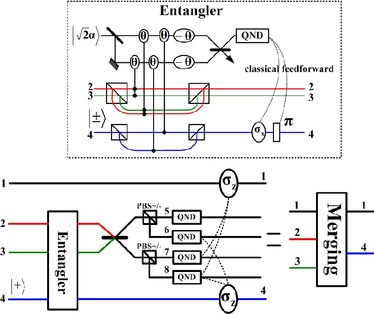
Since the C-Path operation splits the target photon into two different paths, we also require a gate to merge these two paths back into a single path. To perform the conversion deterministically, we introduce another elementary gate called the Merging gate shown in Fig. 2, where an extra ancilla photon is used. It implements the transformation
| (5) |
i.e., the merging of the second photon modes on path 2 and 3 to path 4.
The ancilla photon is in the state . A total state , for example, is first sent to Entangler in Fig. 2, where we let the photons interact with the qubus beams (see the setup in the dashed line of Fig. 2). Similar to the double XPM pattern in C-path gate, the total state will be transformed to
| (6) |
with a bit flip and a phase shifter conditioned on the results of the number-resolving detection on a qubus beam (no action should be taken if ). After the interference of the modes on path 2 and 3, and , through a 50:50 BS, two PBS± let the components be transmitted while having the components reflected, making the single photon run on four different paths numbered from to . We then use the QND modules, which are the same as that in Fig. 1, on each path to determine where the single photon in the state passes. The QND detections therefore project out the outputs, and the projected out photon on one of the paths can be used again in the next Merging gate.
V Two-qubit gates
Two-qubit gates such as CNOT, CZ and C-phase, which are included in the class , can be simply constructed with these elementary gates. Any gate operation in this form is performed by a C-path gate followed by the single qubit operations and on the different paths of the target photon and then a Merging gate. Compared with the qubus mediated CNOT gate in [6], a CNOT gate constructed with a pair of C-path and Merging gate uses the same amount of resources—two elementary gates and one ancilla single photon—without counting the QND modules for resolving the photon numbers in a qubus beam and preserving the ancilla photon in detections. Since we apply the double XPM method in [9], the number of the conditional XPM phase rotations in each elementary gate will be greater than that in [6]. In addition to recycling the qubus beams, the advantage of the double XPM method is that a minus XPM phase shift , which is impractical to realize [11], can be avoided. Moreover, unlike the scheme in [7], there is no need for the displacement operations on the qubus beams, which could be hard to implement if the displacement amplitude is large [12, 13].
VI Multi-qubit gates
It is straightforward to generalize to multiple qubit gates, as any multi-qubit gate is decomposable to a product of two-qubit gates and single-qubit gates [3]. In the framework of realizing quantum computation with the two above-discussed elementary gates, however, the design of a multi-qubit gate can be simplified much further. We illustrate the point with two typical multi-qubit gates—the Fredkin gate and the Toffoli gate.
The schematic setup in Fig. 3 is a Fredkin gate which implements a swap operation on two target photons controlled by the of the control photon. In other words, it performs the following transformation of a triple photon state :
| (8) |
where denotes the unchanged terms. Here we use two C-path gates to map the second photon to path 2 and 3, and the third photon to path 4 and 5:
| (9) |
A deterministic Fredkin gate can be therefore realized by exchanging the modes on path 3 and 5, and using two Merging gates as the inverse operation of two C-path gates. In the implementation of two Merging gates, only one ancilla photon is necessary since it can be used again after QND detection. This feature is especially useful when there are many Merging gates in computation.


The Toffoli gate illustrated in Fig. 4 is the bit flip of a target photon conditioned on both of two control photons, i.e., a triple-qubit operation , where . To implement the gate, we start with a C-path gate for the initial state (in the same form as in Eq. (8)) to send the second photon to two different paths and under the control of the polarizations of the first photon :
| (10) |
Meanwhile, as shown in dashed line of Fig. 4, a 50:50 BS divides the target photon into two paths and . Two qubus beams will be applied to perform the second C-path gate with the control of the modes and on path . There is a slight difference in this C-path gate (denoted as C-path-2 in Fig. 4) from a standard one in Fig. 1—the second beam is coupled not only to the mode on path and the mode on path but also to of the first control photon, while the first beam interacts with the target mode on path and the control mode on path , as indicated in the following transformation:
| (11) |
The remaining operations on two qubus beams are the same as those in a standard C-path gate—two phase shifts and a 50:50 BS. According to the number-resolving detection results on one qubus beam, an output state,
| (12) |
will be deterministically projected out. After that, a bit flip is performed on path alone. The total operation for a deterministic Toffoli gate will be then completed with two Merging gates for the modes on path and , and on path and , respectively.

This design can be generalized to the situation of more than three qubits, where we could simply adopt the similar coupling patterns for the photonic modes in the successive C-path gates. In Fig. 5 we outline a triple-control Toffoli gate of such type, which implements the bit flip of a target photon under the modes of three control photons together. The simplicity of this approach stands out as compared with the conventional method of decomposing a quantum circuit into double-qubit and single-qubit gates. By the conventional method, there should be at least five two-qubit gates for the Fredkin and Toffoli gates [16]. Here we deterministically realize them with only two pairs of C-path and Merging gates, which are equivalent to two double-qubit gates. Generally, there should be two-qubit gates to simulate a multi-control gate of qubits in the decomposition approach [17]. As shown in Fig. 4 and 5, however, we will only need a number of the elementary gates, which grows linearly with the number of the involved qubits, to realize a multi-control gate. The decomposition of a multi-qubit circuit into two-qubit and single-qubit gates is also theoretically complicated. But in our approach the construction of a multi-control gate follows a regular way as from Fig. 4 to Fig. 5.
VII Experimental feasibility
Here we take a brief look at the feasibility of this quantum computation approach. A core technique for realizing the elementary gates is the XPM in Kerr media. Good candidates for weak cross-Kerr nonlinearity without self-phase modulation effects are atomic systems working under electromagnetically induced transparency (EIT) conditions [18]. With light-storage technique, for example, it is possible to realize a considerable XPM phase shift at the single photon level [19]. In principle, however, we only need a small XPM phase shift which can be compensated by the large amplitude of the qubus beams as in [6, 7]. The error probability of a detection in the QND modules is
| (13) |
rendering a near-deterministic performance given . Moreover, there is no XPM phase shift and no displacement operation on the qubus beams. The design is robust against small losses of the photonic modes in the double XPM processes [13], and is workable with the realistic number-non-resolving detectors as we apply the indirect detection of photon numbers.
VIII Summary
The architecture of a quantum computer based on two elementary gates—Controlled-path gate and Merging gate—is relatively simple compared with those of all other approaches. The data to be processed is directly encoded in single photon modes, and the ancilla photon and communication beams are also in simple quantum states so that the possibility for operational errors could be minimized. The recyclable ancillas keep the resources required in multi-qubit computing minimal. Such quantum computer may come into being with the development of the techniques of cross-Kerr nonlinearity and quantum memory for single photon qubits.
Acknowledgements.
B. H. thanks C. F. Wildfeuer for helpful discussion on photon number resolving detections, and the partial support from iCORE.References
- [1] E. Knill, et al., Nature (London) 409, 46 (2001).
- [2] E. Knill, Phys. Rev. A 68, 064303 (2003); T. B. Pittman et al., Phys. Rev. Lett. 88, 257902 (2002); J. L. O’Brien et al., Nature (London) 426, 264 (2003).
- [3] M. A. Nielsen and I. L. Chuang, Quantum Computation and Quantum Information (Cambridge University Press, Cambridge, 2000).
- [4] R. Raussendorf and H. J. Briegel, Phys. Rev. Lett. 86, 5188 (2001); M. A. Nielsen, Phys. Rev. Lett. 93, 040503 (2004); D. E. Brown and T. Rudolph, Phys. Rev. Lett. 95, 010501 (2005).
- [5] P. Kok, et al., Rev. Mod. Phys. 79, 135 (2007).
- [6] K. Nemoto and W. J. Munro, Phys. Rev. Lett. 93, 250502 (2004).
- [7] W. J. Munro et al., New J. Phys. 7, 137 (2005); T. P. Spiller et al., New J. Phys. 8, 30 (2006).
- [8] Q. Lin and J. Li, Phys. Rev. A 79, 022301 (2009).
- [9] B. He, et al., Phys. Rev. A 79, 052323 (2009).
- [10] A. J. Miller, et al., Appl. Phys. Lett. 83, 791 (2003); A. E. Lita, et al., Opt. Express 5, 3032 (2008); C. F. Wildfeuer, et al., arXiv: 0905.1085v2.
- [11] P. Kok, Phys. Rev. A 77, 013808 (2008).
- [12] M. G. Paris, Phys. Lett. A 217, 78 (1996).
- [13] B. He, et al., Phys. Rev. A 79, 035802 (2009).
- [14] N. Khaneja, et al., Phys. Rev. A 63, 032308 (2001); B. Kraus and J. I. Cirac, Phys. Rev. A 63, 062309 (2001); J. Zhang, et al., Phys. Rev. A 67, 042313 (2003).
- [15] F. Vatan and C. Williams, Phys. Rev. A 69, 032315 (2004).
- [16] J. A. Smolin and D. P. DiVincenzo, Phys. Rev. A 53, 2855 (1996).
- [17] A. Barenco, et al., Phys. Rev. A 52, 3457 (1995).
- [18] H. Schmidt and A. Imamoglu, Opt. Lett. 21, 1936 (1996); M. Fleischhauer, et al., Rev. Mod. Phys. 77, 633 (2005).
- [19] Y.-F. Chen, et al., Phys. Rev. Lett. 96, 043603 (2006).