The MEG Spectrometer at PSI
Abstract
The MEG experiment is designed to search the Lepton Flavor Violating process [1, 2]. This search requires a high intensity muon beam stopping in a thin target with the maximum rate compatible with the background from combinatorial events.
The events are analyzed by a high resolution and fast liquid xenon calorimeter and by a spectrometer composed by an array of ultra-light drift chambers (DCH) for momentum measurement and a double layered timing counter (TC) for measuring the time.
The design parameters and performance of the spectrometer during the 2008 physics run are described.
Keywords:
Spectrometer, Rare Decay1 Design parameters of the experiment
The goal of MEG is improving the limit on [3] by two order of magnitude to probe new physics beyond the Standard Model.
The signal has a simple topology: monochromatic and with moving in opposite directions (), originating from the same space-time point.
The physical background comes from the radiative decay with vanishing energy. The accidental background comes from a from Michel decay and a with signal-like kinematic. The may originate from radiative decay, from Bremsstrahlung or from annihilation
In MEG the accidental background dominates. It is proportional to the instantaneous rate , because of coincidence within the time resolution window. The optimal beam configuration is a DC beam with dependent on the detector resolution and background.
The experiment is located at the Paul Scherrer Institut near Zürich, Switzerland that provides the most intense DC beam in the world.
The detection is based on homogeneous liquid xenon calorimeter. The design parameters and performances are discussed in [4].
The spectrometer is designed with an acceptance and the following FWHM resolutions: time , angular momentum and vertex position on target .
2 The beam
The beam is obtained starting from a stopped beam. The from decaying close to the target surface (surface muons) are monochromatic with momentum . They are transported through a Beam Transport Solenoid (BTS) into the MEG detector.
The beam intensity is steerable up to a maximum above . To cope with combinatorial background we use the intensity .
3 The spectrometer
The approach of the MEG spectrometer in satisfying the above design parameters in presence of high rate consists in developing a particular configuration of the magnetic field to sweep out quickly preventing excessive hit crowding in DCH and in minimizing material on path to reduce multiple scattering. The whole spectrometer is embedded in He gas. A display of the spectrometer with a signal event is shown in Fig1a.
3.1 The COBRA magnet
The COnstant Bending RAdius magnet is a thin superconducting magnet with an axial gradient and a central value . This configuration has two advantages: the maximum radius of a trajectory depends mainly on its total and not on its transverse momentum, therefore almost independent from its polar angle, and the emitted at normal polar angle are swept away in a few turns.
3.2 The target
The target is made of polyethylene thick with an ellipsoidal shape. It is located at COBRA center tilted at with the beam axis. Holes with diameter are drilled in the target for easing alignment.
This configuration guarantees that emitted in the spectrometer acceptance suffer low multiple scattering while the fraction of not stopping in the target is minimized: in fact of the entering the BTS decay in the target.
3.3 The Drift Chamber
The momentum is measured with a set of 16 low mass Drift Chambers. They are positioned at fixed with wires along z (beam direction). Design and construction details are presented in [5].
The chamber measures the momentum and kinematic parameters. The measured tracks are extrapolated to match TC hit where their timing is precisely measured and to the target to define the event vertex.
Problems with HV trips reduced significantly the DCH efficiency during the 2008 run and worsened the momentum resolution compared to the design values. Chamber are being redesigned to remove this problem.
3.4 The Timing Counter
The timing counter (TC) is designed to provide trigger information on the momentum, relative direction and time of the . It is divided in two sectors, upstream and downstream the target. Each sector consists of an inner layer made of thick scintillating fibers read by APD and an outer layer made of thick scintillating bars read by PMT insensitive to the magnetic field along their axis.
The PMT output is sampled at 2GHz with a custom designed chip [6, 7] for offline timing reconstruction. The same chip is used for sampling the output of the liquid xenon calorimeter that measured the time.
The inner layer measures the coordinate while the outer one the coordinate and the time. The TC timing resolution is obtained studying events with multiple bar hits. The result of is very close to the design value .
3.5 The Time Calibrations
The TC tight timing requirements need a time intercalibration between bars and with the calorimeter. is measured on the bars and extrapolated to the vertex on the target using the track parameters measured with the DCH. is measured on the inner surface of the calorimeter and extrapolated to the target. and extrapolated to the target are required to match within the experimental resolution.
Each PMT on each bar sides provides a separate and independent measurement of time, related to the impact time on the n-th bar from
where PMT0 is on the inner side and PMT1 on the outer one. is the coordinate along the bar, the effective velocity and the PMT offsets.
For cosmic rays, that hit the bars uniformly in , the distribution of is centered at , so that are measured.
Besides Michel and cosmic rays, that are available with the default setup, we designed two other calibration approaches. In the former, a custom designed Cockroft-Walton accelerator feeding a proton beam with onto a target containing Boron. The reaction delivers two simultaneous with and . The s are detected in the TC and in the calorimeter providing a tool for bar intercalibration.
Another approach consists in delivering a beam on the target to produce through charge exchange process. The Dalitz decay provides - pairs generated from the same vertex. Using as reference, the relative interbar offsets are calculated. The calorimeter-TC offset is also obtained with the same method.
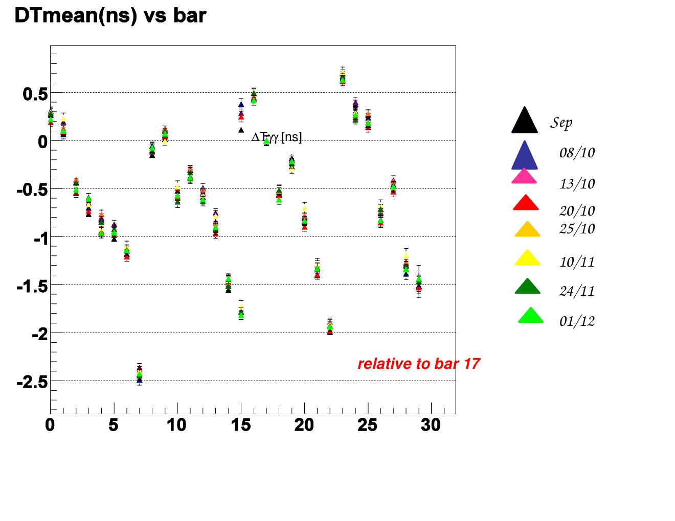
The result of the interbar calibration at different times in Fig.2a shows that the offsets are remarkably stable.


4 The DCH-TC matching
A measurement of requires both the DCH for the kinematic parameters and the TC for the time. The DCH track is extrapolated to the TC surface and matched with a TC hit, that provides information about from the bar position, from the fiber position and from . In Fig.2b the DCH-TC match in is shown with a resolution .
5 Radiative Decay detection
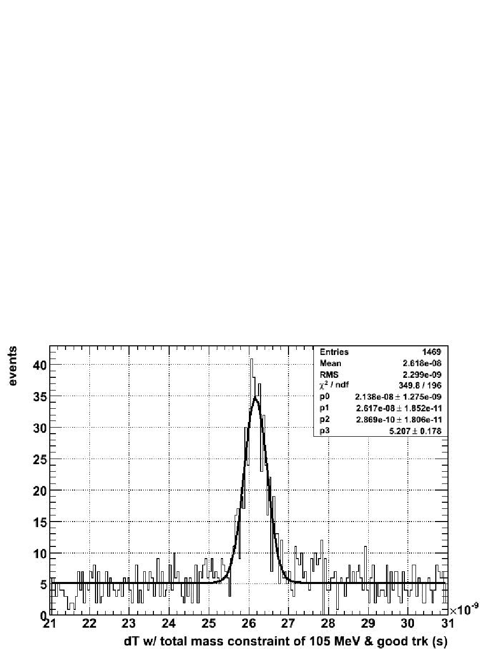
One of the most critical tests of the feasibility of the experiment is its capability of detecting pairs emitted from the same space-time point, distinguishing them from the combinatorial background. These pairs are generated from Radiative Decays with a known Branching Ratio and its detection is a proof of the good time resolution of the spectrometer. In Fig.1b the Radiative Decay peak is clearly visible above the background.
6 Conclusions
The MEG spectrometer was commissioned during 2008. A hardware problem with the DCH limited its efficiency and momentum resolution. Nevertheless several aspects of the spectrometer functionality were successfully tested.
The detection of RD events demonstrates the functionality of the apparatus.
References
- [1] MEG Collaboration T. Mori et al, Research Proposal to PSI R-99-05, 1999
- [2] A. Baldini, Status of the MEG experiment, Nuclear Physics B, Proceeding Supplement 168 (2007) 334
- [3] W. Yao et al., Review of Particle Physics, Journal of Physics G 33 (2006) 1
- [4] R. Sawada, Performance of liquid xenon gamma ray detector for MEG, This proceedings (2009)
- [5] M.P. Hildebrand, The drift chamber system of the MEG experiment, This proceedings (2009)
- [6] S. Ritt, Design and Performance of the of the 5 GHz Waveform Digitizing Chip DRS3, IEEE TNS, 4 (2007) 2485
- [7] S. Ritt, Design and Performance of the of the 6 GHz Waveform Digitizing Chip DRS4, IEEE Nuclear Science Symposium Conference Record (2008)