Broadband Negative Refraction with a Crossed Wire Mesh
Abstract
It is demonstrated that a structured material formed by nonconnected crossed metallic wires may enable negative refraction over a wide frequency range. This phenomenon is a consequence of the anomalous dispersion characteristics of the material, particularly of the fact that the isofrequency contours are hyperbolic. These properties rely on the nonlocal response of the crossed wire mesh, and establish a different paradigm for obtaining negative refraction without left-handed materials.
pacs
42.70.Qs, 78.20.Ci, 41.20.Jb, 78.66.SqI Introduction
Negative refraction has undoubtedly been in the spotlight in recent years. Much of the interest in this fascinating phenomenon is caused by the fact it contradicts our experience that light is bent by common materials (e.g. glass) in a such a way that the projections of the incident and transmitted rays along the interface are oriented in the same direction. It was first predicted by Veselago [1] forty years ago that materials with simultaneously negative permittivity and permeability (“left-handed” materials) may enable negative refraction. However, such exotic materials were unknown at the time, and only some years ago they were made available in the form of metamaterials [2]. Shortly after this finding negative refraction was demonstrated at microwaves [3], but, since structuring materials in the nanoscale is still a true challenge, only very recently negative refraction was finally revealed at optical frequencies using a truly three-dimensional metamaterial [4].
It is well-known that negative refraction may be obtained without left-handed materials. For example, one possibility is to use indefinite anisotropic materials, for which one component of the permittivity is negative [5, 6, 7, 8, 9]. Another possibility is to engineer the dispersion characteristic of photonic crystals [10, 11]. Here, we demonstrate a distinctively different route to obtain all-angle broadband negative refraction using a spatially dispersive material formed by a crossed wire mesh. It is shown that due to the strongly nonlocal response of the structured material the dispersion contours of the propagating mode consist of two hyperbolas, and that this property makes the group velocity (energy flow) to be refracted in an anomalous manner at an interface with air.

The material considered here is a crossed wire mesh of nonconnected metallic wires with radius . The orientation of the two arrays of wires is determined by the perpendicular unit vectors and [Fig. 1a]. It was demonstrated in our previous work [12] that such material may be characterized by an anomalously high index of refraction in the long wavelength limit, and that such property may enable the propagation of very subwavelength guided modes, as demonstrated experimentally in [13]. Recently, we have shown that the resonant excitation of such guided modes may enable subwavelength imaging [14].
Evidently, the crossed wire mesh has an anisotropic electromagnetic response. The results of our previous studies [12, 13, 14] assumed electromagnetic propagation in a plane normal () to the planes of wires. Here, we demonstrate that for propagation along a direction parallel to the planes of wires () the propagation properties may be dramatically different, and may enable negative refraction. To demonstrate these potentials first we will characterize the isofrequency contours of the bulk metamaterial. As reported in [12, 15, 16, 17], in the long wavelength limit the crossed wire mesh may be characterized by the dielectric function ( is the relative permittivity of the host medium), with
| (1) |
where , is the speed of light in vacuum, is the wave vector, , and is the distance between adjacent parallel wires. For simplicity, it is assumed that the wires are perfect conductors. The effect of metallic loss can be easily accounted for using the more general formulae of Ref. [12], and is relatively small provided the radius of the wires is larger than the skin depth of the metal [12], which may be verified through the infrared domain. It is convenient to choose the system of Cartesian axes so that and [see Fig. 1a].
Consider the case in which the electromagnetic wave propagates in the plane, , with magnetic field polarized along (the time variation is suppressed):
| (2) |
The corresponding electric field is given by:
| (3) |
Using the Maxwell’s Equations it is straightforward to verify that the wave vector must follow the dispersion characteristic:
| (4) |
which, using Eq. (1), may be reduced to a polynomial equation of third degree in with :
| (5) |
It may be verified that when the operating wavenumber is much smaller than the plasma frequency, , there is a unique positive solution for . This means that for low frequencies and for a given there is always a propagating mode with electric field in the plane. The isofrequency contours of this propagating mode are represented in Fig. 1b for a material with formed by metallic wires standing in air (). As seen in Fig. 1b and also reported in Ref. [15, 16], for a fixed frequency the isofrequency contours consist of two hyperbolas with asymptotes running along the directions and . These hyperbolic contours resemble in part the isofrequency contours of an indefinite material, however there is an important difference: the isofrequency contour of an indefinite material consists of a single hyperbola [5]. In Fig. 1b we have also represented the electric field vector lines, which are qualitatively similar to those in an indefinite material.

It is well known that hyperbolic contours may enable negative refraction at an interface with air [5, 6, 8, 9]. In order to investigate this possibility, we consider the geometry shown in the inset of Fig. 2, which shows an incoming plane wave illuminating the metamaterial along the direction . The angle of refraction for the energy flow (determined by the Poynting vector) can be calculated using the fact that the projection of the wave vector onto the interface is preserved [10]. Thus, for a given frequency and angle of incidence , the wave vector associated with the transmitted wave is of the form , where is calculated using the dispersion equation (5) 11 1 For frequencies larger than the plasma frequency, it may be possible that a plane wave propagating in air excites two propagating modes in the metamaterial, and thus originates two refracted beams. However in the long wavelength regime considered here, , only a single propagating mode can be excited, and thus there is a single refracted beam.. The Poynting vector is normal to the associated isofrequency contour [18], 22 2 In nonlocal media the Poynting vector can be explicitly calculated as, , where and the “high frequency” component is such that [17, 18]. It is demonstrated in [18] (p. 65-67) that the Poynting vector is given by the product of the energy density and the group velocity.. As in indefinite media, the angle between the wave vector and the Poynting vector in the metamaterial is acute.
In Fig. 2 we show the angle as a function of the angle of incidence , for different frequencies of operation. Consistent with hyperbolic shape of the isofrequency contours, the angle of transmission is negative, i.e. the wave group velocity suffers, indeed, negative refraction at the interface of the crossed wire mesh with air. The results of Fig. 2 indicate that this phenomenon (unlike in photonic crystals and left-handed materials) is very broadband, being observed for a wide range of frequencies. Notice that at the considered frequencies the electrical size of the unity cell of the crossed wire mesh is small, , as required in order that homogenization theory can be applied. The emergence of negative refraction in the crossed wire mesh has a simple physical justification. Indeed, consider the scenario depicted in Fig.1a, which shows the incoming wave illuminating the metamaterial along a direction such that the incoming electric field is nearly parallel to the direction . In these circumstances, it is clear from the topology of the metamaterial that the incoming wave will interact mainly with the set of wires directed along . But since these wires are tilted by with respect to the interface, it is apparent that as the wave propagates in the crossed wire mesh it suffers a negative spatial shift, or in other words, since the dominant path of propagation is expected to be along the wires parallel to , the group velocity suffers negative refraction. Thus, in a certain sense, each set of wires behaves as a waveguide, and the polarization of the incoming wave controls which set of wires is “activated” and which set of wires is “dormant”. This heuristic interpretation is of course only a very rough description of the complex wave interaction between the crossed wires, but enables one to visualize and relate the negative refraction to the microstructure of the material.
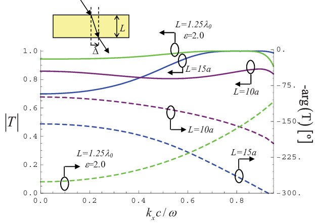
In order to confirm the homogenization results, we used the full wave commercial simulator CST Microwave to calculate the transmission coefficient of a crossed wire mesh slab under plane wave incidence, with magnetic field along the -direction [Fig. 3]. Specifically, we have calculated as a function of (- component of the wave vector of the incoming wave) for a normalized frequency of operation . Notice that is determined by the angle of incidence: . It can be seen in Fig. 3 that the crossed wire mesh is relatively transparent to radiation for all incident angles, and that may be close to unity. This property is observed over a very wide frequency range (not reported here for brevity); in general, the transmissivity tends to improve with increasing frequency. These results indicate that the crossed wire mesh may be well-matched to free-space.
It is interesting to analyze the variation of the phase of with . For convenience, let us write , where . It can be seen in Fig. 3 that is a decreasing function of . Interestingly, such behavior is completely different from that in a conventional dielectric slab with positive permittivity (green dashed line in Fig. 3), for which increases with . Indeed, as proven next, the slope of is equal to the spatial shift suffered by an incoming beam when it crosses the slab [inset of Fig. 3]. In fact, suppose that an incoming beam (e.g. with Gaussian profile) impinges on the planar slab. Suppose that the magnetic field at the input interface is . Using Fourier theory the incoming beam can be written as a superposition of plane waves, as . Evidently, may be regarded as the transfer function of the slab. This means that the magnetic field at the output is such that: . But, if the spatial spectrum of the incoming beam is highly concentrated at the wave number , i.e. if the beam is a quasi-plane wave propagating along the direction , a straightforward analysis (similar to the one used to define group velocity) shows that the magnetic field at the output plane is such that: , where . Therefore, apart from a transmission coefficient, the field at the output plane differs from the field at the input plane from a spatial shift , which is completely determined by the slope of the phase. This analysis is completely general and is valid for an arbitrary material slab. It provides a simple criterion to test the emergence of negative refraction in metamaterials, by testing if is positive or negative. Applying the proposed theory to the crossed wire metamaterial, we see from Fig. 3 that the slope of is negative, and thus it follows that the spatial shift is also negative. This is a direct proof of the emergence of negative refraction in the metamaterial, and fully supports the homogenization results. In particular, for the curve associated with () we have numerically calculated (for incidence along ), (), which indicates that the transmission angle is (). These values concur well the value predicted by homogenization, [Fig. 2].

To demonstrate in a conclusive manner the appearance of negative refraction, we used the Method of Moments (MoM) to simulate numerically the response of a finite width metamaterial slab illuminated by an incoming beam with Gaussian profile. It is assumed in the simulation that both the structured material and the incoming beam are periodic along the -direction, with period equal to . The MoM numerically solves the Maxwell’s Equations and takes into account all the details of the microstructure of the crossed wire mesh, yielding the exact solution of the problem, apart from “numerical noise”. It is assumed in the simulations that each plane of inclusions (parallel to the plane) is formed by 90 wires with radius . As depicted in Fig. 1a, the wires in alternate planes are perpendicular. The Gaussian beam illuminates the slab along the direction , and has a beam waist equal to at the normalized frequency of operation (i.e. ). The width of the slab along is approximately . In Fig. 4 we represent the calculated squared amplitude of the electric field (which is roughly proportional to the beam intensity) in the vicinity of the crossed wire mesh for different thicknesses of the slab. The dashed line represents the propagation path (maximum of the electric field amplitude), and clearly shows that the incoming wave is bent with a negative transmission angle at the interfaces with air. The angle calculated directly from the spatial shift is , , and for panels (a), (b), and (c) of Fig. 4, respectively. These values match relatively well the theoretical value [Fig. 2].
It is interesting to note that the electric field amplitude is significantly lower in the metamaterial slab, as compared to the air regions, particularly in panels (b) and (c) of Fig. 4. One of the reasons is that the field distribution of panels (b) and (c) was calculated at a plane equidistant from two adjacent wire planes, whereas the field distribution of panel (a) was evaluated on a plane with wires. The second reason is that the wave impedance in the crossed wire mesh is lower than in free-space [12], and thus, since beam intensity is roughly , the conservation of energy requires that the squared amplitude of the electric field is lower in the metamaterial. Despite the difference between the impedance in the structured material and free-space, it is evident from the simulations that the level of reflections is relatively weak.
In conclusion, we have demonstrated that a crossed wire mesh may enable negative refraction over a wide frequency band. The described phenomenon does not rely on a resonance of the inclusions, and due to this reason the effect of loss is expected to be relatively small, particularly when the radius of the wires is smaller than the skin depth of metal [12]. A block of the considered material enables negative refraction either if the interface is normal to - or to the - direction. In this regard, the response of the metamaterial is fundamentally different from that of a conventional indefinite anisotropic material, which only yields negative refraction when the interface is normal to the principal axis along which the permittivity is negative. The described results illustrate the richness of the physics of nonlocal materials. This work is supported in part by Fundação para a Ciência e a Tecnologia under project PDTC/EEA-TEL/71819/2006.
References
- [1] V. Veselago, Sov. Phys. Usp. 10, 509 (1968).
- [2] D. R. Smith, W. Padilla, D. Vier, S. Nemat-Nasser, and S. Schultz, Phys. Rev. Lett. 84, 4184 (2000).
- [3] R. A. Shelby, D. R. Smith, and S. Schultz, Science 292, 77 (2001).
- [4] J. Valentine, S. Zhang, T. Zentgraf, E. Ulin-Avila, D. A. Genov, G. Bartal, and X. Zhang, Nature 455, 376 (2008).
- [5] D. R. Smith and D. Schurig, Phys. Rev. Lett. 90, 077405 (2003).
- [6] X. Fan, G. P. Wang, J. C. W. Lee, and C. T. Chan, Phys. Rev. Lett. 97, 073901 (2006).
- [7] A. J. Hoffman, L. Alekseyev, S. S. Howard, K. J. Franz, D. Wasserman, V. A. Podolskiy, E. E. Narimanov, D. L. Sivco, and C. Gmachl, Nature Mat. 6, 946 (2007).
- [8] J. Yao, Z. Liu, Y. Liu, Y. Wang, C. Sun, G. Bartal, A. M. Stacy, and X. Zhang, Science 321, 930 (2008).
- [9] Y. Liu, G. Bartal, and X. Zhang, Optics Express 16, 15439 (2008).
- [10] M. Notomi, Phys. Rev. B 62, 10696 (2000).
- [11] E. Cubukcu, K. Aydin, E. Ozbay, S. Foteinopoulou, and C. M. Soukoulis, Nature 423, 604 (2003).
- [12] M. G. Silveirinha and C. A. Fernandes, Phys. Rev. B 78, 033108 (2008).
- [13] M. G. Silveirinha, C. A. Fernandes, J. R. Costa, and C. R. Medeiros, Appl. Phys. Lett. 93, 174103 (2008a).
- [14] M. G. Silveirinha, C. A. Fernandes, and J. R. Costa, Phys. Rev. B 78, 195121 (2008b).
- [15] M. G. Silveirinha and C. A. Fernandes, IEEE Trans. on Microwave Theory and Tech. 53, 1418 (2005).
- [16] C. R. Simovski and P. A. Belov, Phys. Rev. E 70, 046616 (2004).
- [17] I. S. Nefedov, A. J. Viitanen, and S. A. Tretyakov, Phys. Rev. B 72, 245113 (2005).
- [18] V. Agranovich and V. Ginzburg, Spatial dispersion in crystal optics and the theory of excitons (Wiley- Interscience, NY, 1966).