Elimination of the Diffraction of Arbitrary Images Imprinted on Slow Light
Abstract
We present a scheme for eliminating the optical diffraction of slow-light in a thermal atomic medium of electromagnetically induced transparency. Nondiffraction is achieved for an arbitrary paraxial image by manipulating the susceptibility in momentum space, in contrast to the common approach, which employs guidance of specific modes by manipulating the susceptibility in real space. For negative two-photon detuning, the moving atoms drag the transverse momentum components unequally, resulting in a Doppler trapping of light by atoms in two dimensions.
pacs
42.50.Gy, 42.25.FxEvery classical wave field is subjected to diffraction throughout its propagation. Nondiffracting beams, i.e., optical modes that maintain their intensity distribution in the transverse planes normal to the propagation direction, exist only within the particular class of Bessel beams [1]. There is no solution, in any field in optics, to suppress diffraction for an arbitrary image and for any distance along the propagation direction.
In recent years, the process of electromagnetically induced transparency (EIT) has been employed to reduce or eliminate the diffraction spreading of beamlike fields [2-13] by manipulating the susceptibility in real space and inducing a gradient of the index of refraction [14]. Similarly to waveguiding, special modes, such as the Laguerre-Gauss modes, propagate in the induced waveguides without diffraction or, equivalently, arbitrary images can be revived after a certain self-imaging distance. In this paper, we suggest a method to achieve light propagation without diffraction for any arbitrary paraxial image, with both the intensity and phase information of the image completely maintained. We utilize Dicke narrowing in a vapor EIT medium [15] to obtain a susceptibility that is quadratic in the transverse momentum space and by that eliminate the effect of diffraction. A unique manifestation of nondiffraction is the ability to suspend the expansion of a beam regardless of its position. Other applications may include high-resolution imaging, slowing and storage of images [16, 17], and nonlinear optics [7].
In EIT, a beamlike probe field traverses the medium with a reduced group velocity, in the presence of a second pump field. Spatial manipulation of the probe’s susceptibility may be achieved either by applying a suitable nonuniform pump beam or by employing inhomogeneity of the atomic medium. The former technique, known as electromagnetically induced focusing, was observed in a vapor medium [2] and later with cold atoms [3]. Exact cancellation of diffraction by induced focusing was studied extensively as induced solitons [4], induced waveguides [5, 6], and transverse confinement [7, 8], but in all these investigations was limited to Gaussian or certain higher-order modes. The low group-velocity of each transverse mode is different, resulting in the dispersion of multi-mode profiles, and self-imaging may occur only at certain distances [9]. Waveguiding using an inhomogeneous medium was studied for ultra-cold atoms in an anisotropic trap [10, 11]. Nondiffracting spatial solitons of a specific transverse shape may also be supported by self-focusing or cross-focusing, due to a strong Kerr effect in EIT [12, 13].
Here, we analyze a novel scheme for spatial confinement in the paraxial regime, which incorporates a large plane-wave pump, a uniform atomic spatial distribution, and a weak probe, as opposed to the methods of finite pump, finite atomic cloud, and Kerr solitons, respectively. Instead of imposing transverse nonuniformity in real space, we prescribe nonuniformity in space, such that the paraxial optical diffraction, which is also -dependent, is completely counterbalanced. Here, denotes the transverse wave-vectors, i.e., the Fourier components of the envelope of the field in the transverse plane. We study slow light via EIT in a dilute thermal vapor in the presence of a buffer gas. Due to frequent velocity-changing collisions with the buffer gas atoms, the atomic motion is diffusive, leading to the phenomena of Dicke narrowing and diffusion of light [18]. For a finite-sized probe and a plane-wave pump, the atoms effectively ”carry” the complex amplitude of the probe field within their internal coherence as they diffuse, resulting in an effective diffusion of the probe’s envelope [19, 16]. In this letter, we show that by introducing a nonzero two-photon (Raman) detuning, the atomic motion also induces a -dependence of the refraction index. Specifically, for negative Raman detuning, the -dependent refraction takes the shape of the paraxial diffraction with an opposite sign, thus enabling its cancellation. This diffraction elimination is homogenous and continuous, as opposed to discrete diffraction-management techniques [20].
The following simplified picture, illustrated in Fig. 1(a), explains this spatial-confinement phenomenon. Generally, for a negative detuning, a moving atom couples more efficiently with the ’counter-propagating components’ (wave vectors) of the field due to the Doppler effect. In EIT, a residual Doppler effect takes place, which depends on the wave vector associated with the difference between the pump and the probe [15, 21]. In the simplest arrangement – a plane wave, degenerate, and co-propagating pump – the pump-probe wave-vector difference equals . Therefore, for negative Raman detuning, each component in space exhibits stronger coupling with the atoms moving in the direction and is effectively carried back towards the main axis. This is, in fact, a realization of a Doppler trapping of light by atoms, in analogy with the trapping of atoms in a Doppler optical trap.
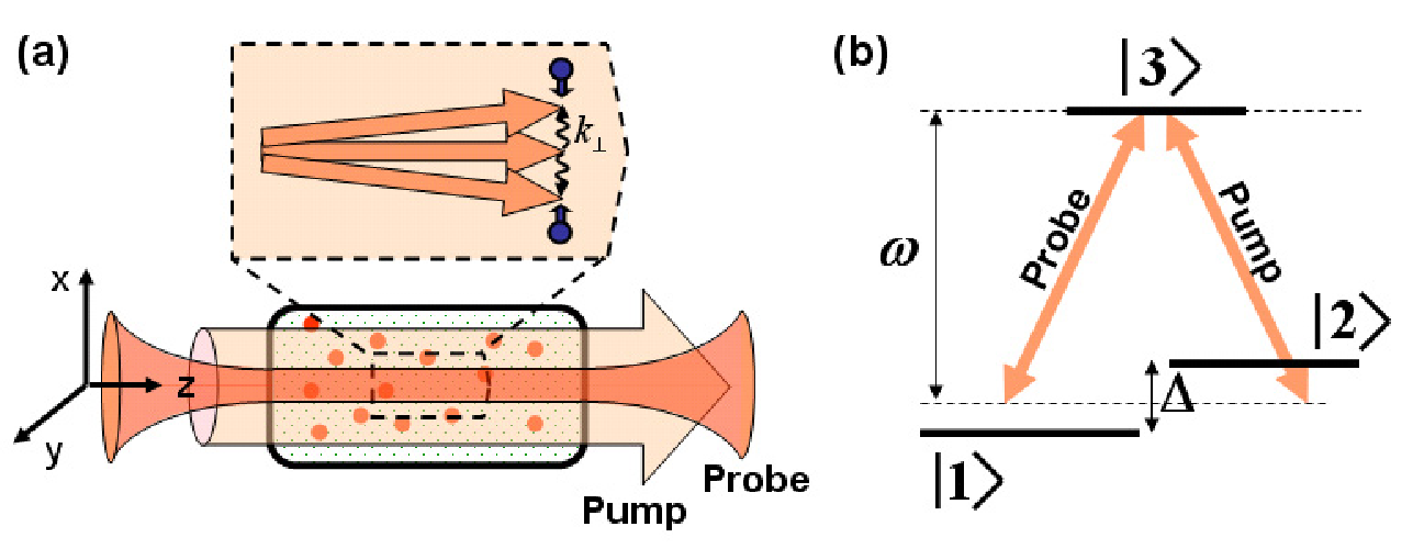
Consider a dilute vapor of -type atoms, with two nearly-degenerate lower states, and , and a single excited state . A probe beam and a strong plane-wave pump propagate along the direction, with equal frequency and couple states and with state , respectively (see Fig. 1b). The energy difference between the lower levels, , defines the Raman detuning 11 1 All the results are essentially unchanged when a small pump-probe frequency difference is introduced., and the one-photon detuning is assumed to be much smaller than the width of the optical resonance. Under the paraxial approximation, assuming the changes in the probe’s envelope along the direction are much smaller than the changes in the transverse plane, and assuming the pump is nearly constant along , the propagation of the probe in steady state can be described by [18],
| (1) |
where , is the speed of light, and is the linear susceptibility, with being the absorption coefficient and being dispersion. is the Fourier transform of the slowly varying Rabi envelope of the probe, defined by
| (2) |
with the rapidly oscillating Rabi frequency. The second summand in the left-hand side of Eq.(1) is the well-known diffraction term, which is quadratic in and purely imaginary.
For an atom at rest, the susceptibility in the vicinity of the EIT line is where is the absorption coefficient in absence of the pump; is the power-broadening term, proportional to the pump intensity; and is the total homogenous EIT line width – the sum of and the decoherence rate within the ground-state manifold. In a vapor medium with buffer gas, the EIT atoms are subjected to frequent velocity-changing collisions with the buffer-gas atoms 22 2 Spin-exchange collisions between the EIT atoms are much less frequent and are taken into account in the homogenous EIT width .. The resulting atomic motion is diffusive and is characterized by a diffusion coefficient , incorporating both the mean thermal-velocity and the collision rate. Due to residual Doppler broadening and Dicke narrowing, the EIT line shape becomes dependent on the two-photon wave-vector difference, , and the resulting susceptibility is [18]
| (3) |
The term is the Doppler-Dicke width, originating from the atomic motion 33 3 In Eq.(3), the parameters and are somewhat different from those for an atom at rest and incorporate the atomic motion [18]..
On the Raman resonance, , the susceptibility is pure imaginary and thus generates a -dependent absorption filter without dispersion. The absorption filter for , depicted in Fig. 2 (dashed black), is a Lorentzian of width When the spatial spectra of the probe beam is confined within the absorption is approximately quadratic in and, according to Eqs. (1) and (2), operates as a Laplacian in real space, and causes a diffusion-like behavior [18].

For , the absorption and the dispersion for nonzero Raman detuning can be written as
| (4a) | ||||
| (4b) | ||||
| At the central part of the spatial spectrum, the dispersion is quadratic in exactly like a paraxial diffraction term. Therefore, by properly choosing the parameters, the dominant part of the motional-induced dispersion, namely the term, can cancel the free-space diffraction. The strength and the sign of the dispersion depend on , and, in order to eliminate diffraction, a non-zero negative detuning is required. For the specific case of the absorption filter in Eq.(4a) is flat up to the fourth order in , as seen in Fig. 2 (top, solid red), implying that no motional-induced diffusion will accompany the propagation of paraxial images. By this we avoid spreading due to absorption, which was significant, for example, in electromagnetically induced focusing [22]. We therefore choose and, following Eq. (1), require the diffraction cancellation condition: | ||||
| (5) |
Under regular diffraction, a focused Gaussian beam that hits the medium with a waist radius spreads as , with being the Rayleigh length. Condition (5) can be intuitively explained, by requiring the diffraction spreading at one Rayleigh length () to be comparable to the typical diffusion spreading (, where is the slow-light delay and is the group velocity). For a waist of m and a Rayleigh length of a few cm, conditions (5) and can be satisfied with of the order of cm2/s and of km/s, which are readily available [19, 16]. Notice however, that due to the deviation from the Raman resonance-condition, the absorption per unit length, , is substantial. It becomes smaller as the power-broadening increases and eventually approach for . For a beam with and for condition (5) becomes , which means the intensity decreases by about every Rayleigh length.
In our scheme, strong absorption is unavoidable due to the non-zero Raman detuning. While an observation of the non-diffraction phenomenon is well within current experimental capabilities, applications of it may require smaller absorption. Here, the fact that the absorption is independent of is crucial, allowing a wide range of gain schemes to be potentially applicable. Homogenous gain mechanisms that are available for vapor, e.g. Raman gain 44 4 See, e.g., J. A. Kleinfeld and A. D. Streater, Phys. Rev. A 49, R4301 (1994). By the addition of another vapor species, with Raman gain properties, the absorption may be compensated by controlling the relative atomic densities. The two-photon bandwidth of the Raman resonance should be much larger than the Dicke line-width of the image, to ensure the gain uniformity in space., can be considered, and specifically two integrated gain schemes in EIT were recently explored 55 5 I. Novikova, D. F. Phillips, and R. L. Walsworth, Phys. Rev. Lett. 99, 173604 (2007). This gain is phase dependent. However, we have numerically simulated its operation and showed that, thanks to the non-diffraction process, the relevant phase is spatially conserved and the gain is uniform.[23]. There is also the trivial possibility to introduce gain before or after the cell, providing the gain medium is much thinner than the Rayleigh length.

Figure 3 presents numerical calculations of the effect, obtained by taking the Fourier transform of the boundary condition, , according to Eq. (2), solving Eq. (1), and doing the inverse Fourier transform. The exact expression (3), rather than the approximation of Eqs. (4a) and (4b), was used for the calculation. Figure 3(a) demonstrates the transmission of two Gaussian beams in the transverse plane at , and Fig. 3(b) depicts the propagation of three beams along the axis up to . Without EIT (left column), there is only free-space diffraction, and with EIT on-resonance ( center column), the diffraction spreading is accompanied by a diffusion spreading, due to the -dependence of . For EIT with (right column), the elimination of spreading due to both diffraction and diffusion is clearly evident. Notice that the width of each Gaussian beam in Fig. 3(b) increases by after . This is the effect of fourth order in and we have verified numerically that the spreading after Rayleigh lengths approaches zero as is increased (e.g., for a waist of the spreading is ). An example of nondiffraction of an elaborated image that traverses is presented in Fig. 4. As evident from Figs. 3 and 4 and in contrast to previous nondiffraction schemes, our scheme works for a general image and for any distance along the propagation direction.

In conclusion, we utilize the EIT linear susceptibility in the wave-vector space, rather than in real space, to eliminate the diffraction of a paraxial probe beam with a general transverse profile, limited in -space to the region . From the viewpoint of optical information processing, our scheme may be useful to increase the capacity of information carried by the slow-light and hence also the memory capacity in storage of light. As is increased and is decreases, the resolution of the nondiffracting pattern may be increased. Elongated narrow beams can also be utilized for the purpose of guiding, for example, via non-linear interactions or dipole trapping. An intriguing extension of this work would be to generalize the two-dimensional ’Doppler trap’ to pulses of finite duration, in order to achieve trapping in three dimensions.
References
- [1] J. Durnin, J. Opt. Soc. Am. A 4, 651 (1987).
- [2] R. R. Moseley et al., Phys. Rev. Lett. 74, 670 (1995).
- [3] M. Mitsunaga, M. Yamashita, and H. Inoue, Phys. Rev. A 62, 013817 (2000).
- [4] D. Bortman-Arbiv, A. D. Wilson-Gordon, and H. Friedmann, Phys. Rev. A 58, R3403 (1998).
- [5] R. Kapoor and G. S. Agarwal, Phys. Rev. A 61, 053818 (2000).
- [6] A. G. Truscott et al., Phys. Rev. Lett. 82, 1438 (1999).
- [7] A. Andre et al., Phys. Rev. Lett. 94, 063902 (2005).
- [8] J. Cheng, S. Han, and Y. Yan, Phys. Rev. A 72, 021801(R) (2005).
- [9] J. Cheng and S. Han, Opt. Lett. 32, 1162 (2007).
- [10] M. Vengalattore and M. Prentiss, Phys. Rev. Lett. 95, 243601 (2005).
- [11] D. Tarhan, N. Postacioglu, and Özgür E. Müstecaplioglu, Opt. Lett. 32, 1038 (2007).
- [12] T. Hong, Phys. Rev. Lett. 90, 183901 (2003).
- [13] I. Friedler et al., Opt. Lett. 30, 3374 (2005).
- [14] C. Gómez-Reino and E. Larrea, Appl. Opt. 21, 4271 (1982).
- [15] O. Firstenberg et al., Phys. Rev. A 76, 013818 (2007).
- [16] M. Shuker et al., Phys. Rev. Lett. 100, 223601 (2008).
- [17] P. K. Vudyasetu, R. M. Camacho, and J. C. Howell, Phys. Rev. Lett. 100, 123903 (2008).
- [18] O. Firstenberg et al., Phys. Rev. A 77, 043830 (2008).
- [19] R. Pugatch et al., Phys. Rev. Lett. 98, 203601 (2007).
- [20] H. S. Eisenberg et al., Phys. Rev. Lett. 85, 1863 (2000).
- [21] M. Shuker et al., Phys. Rev. A 76, 023813 (2007).
- [22] R. R. Moseley et al., Phys. Rev. A 53, 408 (1996).
- [23] A. Eilam, A. D. Wilson-Gordon, and H. Friedmann, Opt. Lett. 33, 1605 (2008).