A quantitative investigation of the effect of a close-fitting superconducting shield on the coil-factor of a solenoid
Abstract
Superconducting shields are commonly used to suppress external magnetic interference. We show, that an error of almost an order of magnitude can occur in the coil-factor in realistic configurations of the solenoid and the shield. The reason is that the coil-factor is determined by not only the geometry of the solenoid, but also the nearby magnetic environment. This has important consequences for many cryogenic experiments involving magnetic fields such as the determination of the parameters of Josephson junctions, as well as other superconducting devices. It is proposed to solve the problem by inserting a thin sheet of high-permeability material, and the result numerically tested.
pacs
07.55.Nk, 85.25.Cp, 41.20.GzMany experiments characterizing superconductors and superconducting devices involve applying a magnetic field. One typical class of such experiments is the characterization of Josephson junctions[1].
Superconducting shields are unsurpassed to prevent extraneous AC and DC magnetic fields, e.g., high frequency magnetic noise and the Earth’s magnetic field, from affecting magnetically delicate cryogenic instruments and experiments. However, in order to measure the magnetic properties of specimens in such setups, one has to mount one or more solenoids inside the shield. Often the trade off between demands for homogeneous fields and limited space places the coil in close vicinity of the shield. It is not surprising[2] - but often forgotten - that a shield which is close-fitting around the coil may strongly deform the magnetic field lines and thus change the coil factor, .
It is common practice to use a Hall probe at room temperature to calibrate coils for magnetic measurements, even when the coils are to be used in a cryogenic environment[3]. From this calibration it is possible to determine the coil factor, , relating the DC coil current, , to the B-field, in the center of the solenoid
The problem arises when the coil is consequentially enclosed in a superconducting magnetic shield. For an ideal high-permeability shield, with , the problem does not arise, as the effect of the magnetically soft shield is to create a virtual, free space for the field lines.
First we consider the case of the infinite solenoid in free space and then compare to an infinite solenoid in an infinite, cylindrical superconducting shield. In free space, the internal field of the solenoid can be determined directly from simple, proven theoretical expressions. If Ampere’s Law is integrated along loop number 2 in Fig. 1, it can be seen that the field outside the infinite solenoid, , in free space is everywhere zero, as it must be zero at . Similarly, for loop number 1, the field must be constant everywhere inside the volume enclosed by the solenoid.
If we now apply Ampere’s Law to loop 3 in the figure, it can be seen that the field inside the solenoid, , is given by
| (1) |
where is the current density (per unit length) of the coil. Eq.(1) is valid regardless of the presence of a superconducting shield on the outside.

For the infinite solenoid inside a superconducting shield we simply note, that for a close-fitting superconducting shield (), . This is because the field lines must close on themselves, and now have a limited volume in which to do so. Enclosing an infinite solenoid in a close-fitting ideal superconducting shield () increases , while the field inside the solenoid is reduced. Flux conservation gives:
| (2) |
where the areas and are the cross-sectional areas, between the coil and shield and inside the coil, respectively. From Eqs.(1) and (2) we find:
| (3) |
if the width of the coil is negligible. Eq.(3) has been normalized to the free space value, .
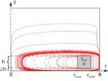
Using Comsol Multiphysics[4] finite-element magnetostatic simulations, the effect of enclosing a finite solenoid with a fixed in a superconducting shield has been investigated. The coil has the parameters mmmmmm, where is the height (see Fig. 2). The distance between the end of the coil and the bottom of the superconducting shield can is denoted . Furthermore, the current, , is DC, which implies a uniform current density in the coil cross-section.
The problem is axisymmetric and the boundary conditions are set to magnetic insulation on the boundary of the superconducting shield. In principle, the shield top should be open, but the simulation is faster, and the difference in the result is within the error of the simulation, by setting the top boundary condition to magnetic insulation as well. The reason is, of course, that it is sufficiently far away, that only a negligible portion of the magnetic field lines would go in this area, even if it was open. The meshing was done automatically, and increasing the mesh density did not alter results.
The geometry used in the simulation is shown in Fig. 2. The magnetic field lines are drawn on top of the geometry. The maximum value of the field is located approximately at the same position, regardless of the coil’s position in relation to the shield.
The results of simulations for a large number of geometries are shown in Fig. 3. The plot shows the maximum value of the magnetic field strength inside the coil as a function of the bottom distance, , and the radial distance, , between the solenoid and the superconducting shield.

The results show a strong influence of the superconducting shield on the generated magnetic field strength. In fact, a radial spacing between the solenoid and the superconducting shield of around is needed to reach 90% of .
The deciding factor appears to be the radial distance, , as even a rather large only gives a 10% increase in field. The effect is larger for larger .
The results show a very weak dependence on and thus we should expect good agreement with the theoretical expression in Eq.(3). For fitting purposes, an additional parameter, , is introduced to deal with the solenoid being finite, and the nearby capped end of the shield:
| (4) |
Fig. 4 is a comparison of Eq. (4) and the simulation output for one value of . The fitting parameters are and the value of , and the best fit is found for mm. Considering the crudeness of the model the fit is acceptable. It also produces a reasonable value for .
The main effect of the cap on the closer end of the shield is to slightly change the limiting value for , and thus , as seen in Fig. 3.

The effect of a high-permeability shield inside the superconducting shield is similar to inserting a large virtual volume of magnetic vacuum. The virtual volume is a factor of thicker than the actual shielding material, and should thus mediate the effect of confinement by the superconducting shield. The high-permeability sheet has been modeled as a cylinder with , which is the stated value for Cryoperm[5] 10 typically used for cryogenic shielding. The result of inserting a mm thick cylinder between the solenoid and the superconducting shield is a full recovery of the of the coil factor to the value obtained for . Also, with the cylinder inserted, is insensitive to the value of . This is reasonable, as mm of high-permeability metal with should be roughly equivalent to m of vacuum between the solenoid and the superconducting shield.
The field strength outside the solenoid can exceed the field strength inside, when is very small compared to . This means, that the critical field of the superconducting shield might be reached before expected. This may introduce hysteresis into measurements as well as large trapped magnetic fields. This can also be countered by the use of a cryoperm sheet.
In this paper we have presented a commonly overlooked source of systematic error in cryogenic setups involving magnetic fields. It was shown, that systematic errors in the coil factor of at least an order of magnitude can be realized in setups with radial shield distance , when comparing to a simple Hall-probe measurement coil factor or standard free-space formulae. Furthermore, an approximate theoretical expression was derived for estimating the real magnetic field or coil factor inside a solenoid enclosed in a superconducting shield.
The most important parameter is the radial distance between the solenoid and the shield. The dependence on the distance from the coil to the shield in the axial direction is very weak - even to the limit of very small values of . The solution is to either make ample space around the coil inside the superconducting shield or insert a high-permeability metal sheet between the coil and the superconducting shield. The effect of the sheet is effectively to insert a virtual vacuum for the magnetic field lines to close in, thus screening the coil from the effect of confinement. In any case, this shows the importance of calibrating the solenoid in situ. In situ calibration can be done using a SQUID magnetometer, without a high-permeability metal shield, if the maximum attainable field in the solenoid is not the limiting factor.
References
- [1] R. Broom, J. Appl. Phys. 47 (1976).
- [2] S. Pourrahimi, J. Williams, W. Punchard, J. Tuttle, M. DiPirro, E. Canavan, and P. Shirron, Cryogenics 48, 253 (2008).
- [3] J. Rowell, Phys. Rev. Lett. 11 (1963).
- [4] www.comsol.com
- [5] Manufactured by Vacuumschmelze Gmbh., datasheet at http://www.amuneal.com/pages/pdf/AmunealDataSheet2.pdf