Bootstrapping Key Pre-Distribution:
Secure, Scalable and User-Friendly Initialization of Sensor Nodes
Abstract
To establish secure (point-to-point and/or broadcast) communication channels among the nodes of a wireless sensor network is a fundamental task. To this end, a plethora of (so-called) key pre-distribution schemes have been proposed in the past [1][2][3][4][5]. All these schemes, however, rely on shared secret(s), which are assumed to be somehow pre-loaded onto the sensor nodes.
In this paper, we propose a novel method for secure initialization of sensor nodes based on a visual out-of-band channel. Using the proposed method, the administrator of a sensor network can distribute keys onto the sensor nodes, necessary to bootstrap key pre-distribution. Our secure initialization method requires only a little extra cost, is efficient and scalable with respect to the number of sensor nodes. Moreover, based on a usability study that we conducted, the method turns out to be quite user-friendly and easy to use by naive human users.
I Introduction
Wireless sensor nodes and sensor networks (WSN) have numerous applications in monitoring diverse aspects of the environment. Ready examples include monitoring of: structural/seismic activity, wildlife habitat, air pollution, border crossings, nuclear emission and water quality. In some applications, sensor nodes operate in a potentially hostile environments and security measures are needed to inhibit or detect sensor node compromise and/or tampering with inter-node or node-to-sink communication. A large body of literature has been accumulated in the last decade dealing with many aspects of sensor network security, e.g., key management, secure routing and DoS detection [6, 7, 2, 8].
In a WSN environment, the nodes might need to communicate sensitive data among themselves and with the sink (also referred to as “sink”). The communication among the nodes might be point-to-point and/or broadcast, depending upon the application. These communication channels are easy to eavesdrop on and to manipulate, raising the very real threat of the so-called Man-in-the-Middle (MiTM) attacker. A fundamental task, therefore, is to secure these communication channels.
Key Pre-Distribution and the Underlying Assumption. A number of so-called “key pre-distribution” techniques to bootstrap secure communication in a WSN have been proposed [1, 2, 3, 4, 5]. However, all of them assume that, before deployment, sensor nodes are somehow pre-installed with secret(s) shared with other sensor nodes and/or the sink. The TinySec architecture [9] also assumes that the nodes are loaded with shared keys prior to deployment. This might be a reasonable assumption in some, but certainly not all, cases. Consider, for example, an individual user (Bob) who wants to install a sensor network to monitor the perimeter of his property. He purchases a set of commodity noise-and-vibration sensor nodes at some retailer and wants to deploy the sensor nodes with his home computer acting as the sink. Being off-the-shelf, these sensor nodes are not sold with any built-in secrets. Some types of sensor nodes might have a USB (or similar) connector that allows Bob to plug each sensor node into his computer to perform secure initialization. This would be immune to both eavesdropping and MiTM attacks. However, sensor nodes might not have any interface other than wireless, since having a special “initialization” interface influences the complexity and the cost of the sensor node. Also, note that Bob would have to perform security initialization manually and separately for each sensor node. This is not scalable since potentially many sensor nodes might be involved.
Also, it is important to note that keys can not always be pre-loaded during the manufacturing phase because eventual customers might not trust the manufacturer. Moreover, a PKI-based solution might be infeasible as it would require a global infrastructure involving many manufacturers.11 1 The problem that we consider in this paper is very similar to the problem of “device pairing”, the premise of which is also based on the fact that the devices wanting to communicate with each other do not share any pre-shared secrets or a common PKI with each other [10].
Secure Initialization Approach. Therefore, the best possible strategy would be for the network administrator to himself/herself perform the key distribution on-site. Due to lack of hardware interfaces (such as USB interfaces) on sensor nodes and for usability reasons, this key distribution should be performed wirelessly. Prior key pre-distribution schemes assume the existence of some pre-installed secret (such as a point on a bivariate polynomial in [4]) using which the shared keys can be derived. Therefore, the task of key distribution is reduced to establishing a secure channel between the administrator’s computer (the sink node) and each node. The resulting secure channels can in turn be used to securely transfer, from the sink to each node, the shared secrets necessary to bootstrap key pre-distribution. Since the administrator might need to initialize a large number of sensor nodes, the process needs to be repeated in batches. The larger the number of sensor nodes in each batch, the more scalable is the secure initialization method.
Prior Work: Message-In-a-Bottle. A sensor network initialization method, called “Message-In-a-Bottle” (MiB), with the above properties was recently proposed by Kuo et al. [11]. In MiB, the key distribution takes place inside a Faraday Cage, which is used to shield communication from eavesdropping and outside interference. MiB can support key distribution onto multiple sensor nodes22 2 Although it is not clear how many motes at one time. in a batch and from the administrator’s perspective, it is quite user-friendly. However, it has some drawbacks. The first problem is the need to obtain and carry around a specialized piece of equipment – a Faraday Cage. As illustrated in [11], building a truly secure Faraday Cage is a challenge. The cost and the physical size of the Cage can be problematic. In other words, only a very few sensor motes could be supported in each batch with a reasonably priced and reasonably sized cage. The second drawback with MiB is that if the initialization process fails for only one sensor node or if there is an error (e.g., if the cage was not properly closed), the entire batch of sensor nodes needs to be re-initialized and re-keyed from scratch. Third, a batch of sensor motes must consist of homogeneous sensor motes with similar weights (the weight is used to calculate the number of motes inside the Cage [11]). Fourth, at least one additional mote (called “keying device”) that possesses a physical interface, such as USB connector, is needed. This increases both the cost and the complexity of the system.
Out-of-Band Channels. To address the aforementioned drawbacks with MiB, we consider an alternative approach based on out-of-band (OOB) channels. The OOB (audio, visual or tactile) channels have recently been utilized in the context of secure device pairing application [10, 12, 13, 14], used to establish shared keys between two previously un-associated devices (we review these methods in Section II). Unlike the wireless communication channel, the OOB channels are both perceivable and manageable by the human user(s) operating the devices, and thus can be used to authenticate information exchanged over the wireless channel. Unlike the wireless channel, the attacker can not remain undetected if it interferes with the OOB channel (although it can still eavesdrop).
Our Contributions. Based on the protocol of Saxena et al. [14], we develop a novel initialization method using a visual OOB channel. The underlying visual channel consists of blinking LEDs33 3 Most commercially available sensor motes possess multiple (typically three) LEDs. (Refer to Mica2 specifications: http://www.xbow.com/Products/Product_pdf_files/Wireless_pdf/MICA2_Datasheet.pdf) as transmitters on sensor nodes and a video camera on the administrator’s computer. The design of such a channel using multiple LEDs solves an open problem posed in [14] and finds a useful application in the context of key distribution for a sensor network.
Based on our current experiments, we show that with a cheap web cam connected to a laptop computer, we are efficiently able to use the above visual channel to securely initialize 16 sensor nodes per batch. In addition, we perform a usability testing of the proposed method, which shows that the method is both user-friendly as well as robust to errors.
II Related Work
The problem of secure sensor node initialization has been considered only recently. Prior to MiB method of [11] (which we reviewed in the previous section), the following schemes were proposed. The “Shake-them-up” [16] scheme suggests a simple manual technique for pairing two sensor nodes that involves shaking and twirling them in very close proximity to each other, in order to prevent eavesdropping. While being shaken, two sensor nodes exchange packets and agree on a key one bit at a time, relying on the adversary’s inability to determine the sending node. However, it turns out that the sender can be identified using radio fingerprinting [17] and the security of this scheme is uncertain.
Another two related schemes are: “Smart-Its Friends” [18] and “Are You with Me?” [19]. Both use human-controlled movement to establish a secret key between two devices. In addition to having the same problems as “Shake-Them-Up”, these schemes require an accelerometer on each sensor node to measure movement. Most sensor nodes can not afford to have accelerometers.
The initialization method that we propose in this paper is similar to the device pairing schemes that use an OOB channel. Thus, we also review most relevant device pairing methods and argue whether or not they can be extended for the application of sensor node initialization. In their seminal work, Stajano and Anderson [20] proposed to establish a shared secret between two devices using a link created through a physical contact (such as an electric cable). As pointed out previously, this approach requires interfaces not available on most sensor motes. Moreover, the approach would be unscalable.
Balfanz, et al. [10] extended the above approach through the use of infrared as an OOB channel – the devices exchange their public keys over the wireless channel followed by exchanging (at least -bits long) hashes of their respective public keys over infrared. Most sensor motes do not possess infrared transmitters. Also, infrared is not easily perceptible by humans.
Based on the protocol of Balfanz et al. [10], McCune et al. proposed the “Seeing-is-Believing” (SiB) scheme [12]. SiB involves establishing two unidirectional visual OOB channels – one device encodes the data into a two-dimensional barcode and the other device reads it using a photo camera. To apply SiB for sensor node initialization, one would need to affix a static barcode (during the manufacturing phase) on each sensor node, which can be captured by a camera on the sink node. However, this will only provide unidirectional authentication, since the sensor nodes can not afford to have a camera each. Note that it will also not be possible to manually input on each sensor node the hash of the public key of the sink, since most sensor nodes do not possess keypads and even if they do, this will not scale.
Saxena et al. [14] proposed a new scheme based on visual OOB channel. The scheme uses one of the protocols based on Short Authenticated Strings (SAS) [21], [22], and is aimed at pairing two devices (such as a cell phone and an access point), only one of which has a relevant receiver (such as a camera). The protocol is depicted in Figure 1 and as we will see in the next section, this is the protocol that we utilize in our proposal. In this paper, we extend the above scheme to a “many-to-one” setting applicable to key distribution in sensor networks. Basically, the novel OOB channel that we build consists of multiple devices blinking their SAS data simultaneously, which is captured using a camera connected to the sink.
Recently, Soriente et al. [23] consider the problem of pairing two devices based on an audio channel. Their scheme can be based on the protocol of [14], with the unidirectional SAS channel consisting of one device encoding its SAS data into audio, and the other device capturing it using a microphone. Extending this scheme to initialize multiple sensor nodes in a scalable manner seems hard as it will be hard to decode simultaneously “beeping” nodes.
Pick Pick Accept as ’s public key if Accept as ’s public key if : the wireless channel : the unidirectional channel : the channel : the channel : public keys of devices and commit() and open(): functions of a commitment scheme based on random oracle model (in practice, SHA-1/MD5) : hash function drawn from an almost universal hash function family
III Communication and Security Model, and the Underlying Protocol
Model. The protocol that we utilize in our initialization method is based upon the following communication and adversarial model [27]. The devices being paired are connected via two types of channels: (1) a short-range, high-bandwidth bidirectional wireless channel, and (2) auxiliary low-bandwidth physical OOB channel(s). Based on device types, the OOB channel(s) can be device-to-device (), device-to-human () and/or human-to-device (). An adversary attacking the pairing protocol is assumed to have full control on the wireless channel, namely, it can eavesdrop, delay, drop, replay and modify messages. On the OOB channel, the adversary can eavesdrop on but can not modify messages. In other words, the OOB channel is assumed to be an authenticated channel. The security notion for a pairing protocol in this setting is adopted from the model of authenticated key agreement due to Canneti and Krawczyk [28]. In this model, a multi-party setting is considered wherein a number of parties simultaneously run multiple/parallel instances of pairing protocols. In practice, however, it is reasonable to assume only two-parties running only a few serial/parallel instances of the pairing protocol. For example, during authentication for an ATM transaction, there are only two parties, namely the ATM machine and a user, restricted to only three authentication attempts. The security model does not consider denial-of-service (DoS) attacks. Note that on wireless channels, explicit attempts to prevent DoS attacks might not be useful because an adversary can simply launch an attack by jamming the wireless signal.
In a communication setting involving two users restricted to running three instances of the protocol, the SAS protocol of [14] need to transmit only () bits of data over the OOB channels. As long as the cryptographic primitives used in the protocols are secure, an adversary attacking these protocols can not win with a probability significantly higher than (). This gives us security equivalent to the security provided by 5-digit PIN-based ATM authentication.
Protocol. The protocol that we utilize [14] is depicted in Figure 1 (we base the protocol upon the SAS protocol of [21], although it can similarly work with other SAS protocol [22] as well). The protocol works as follows. Over the wireless channel, devices A (sensor node) and B (sink) follow the underlying SAS protocol. Then a unidirectional OOB channel is established by device A transmitting the SAS data, over the channel. This is followed by device B comparing the received data with its own copy of the SAS data, and transmitting the resulting bit b of comparison over the -bit OOB channel (say, displayed on its screen). Finally, the user reads the transmitted bit and accordingly indicates the result to device A by transmitting the same bit over an input channel.
For our application of secure initialization of sensor nodes, we execute the protocol of [14] in a “many-to-one” setting. Basically, the sink runs serial or (preferably) parallel instances of the pairing protocol over the wireless channel with each of the sensor nodes belonging to a batch. The SAS data, however, is transmitted simultaneously from each sensor node to the sink. Since the SAS data is transmitted simultaneously by each sensor node, the sink has no efficient way to figure out what SAS value was transmitted by which of the sensor nodes it discovered over the wireless channel. Therefore, the sink accepts the key distribution on a particular sensor node A if the SAS value (derived from information transmitted over the wireless channel) corresponding to A matches with any of the SAS values received over the SAS channel. Sensor node A is therefore accepted with a probability at most instead of as in the original “one-to-one” setting. One can show that such a “many-to-one” variant can be proven secure. In other words, one can show that if there exists an adversary who breaks, with a probability significantly better than , the above many-to-one variant of the protocol of [14], then there exists another adversary who can break the protocol of [14] with a probability significantly better than . We omit this proof in this paper and concentrate on the design and implementation of the underlying SAS channel, using multiple LEDs and a video camera. Note that in order to achieve the same level of security offered by a 5-digit PIN-based authentication (as mentioned above), the length of the SAS data should now be .
The security of our initialization method is equivalent to the security of the underlying SAS protocol, under the assumption that the administrator correctly discards the sensor nodes based on the result (bit corresponding to each sensor node) indicated by sink.
IV Our Proposal: Secure Initialization using a Visual Channel
In this section, we describe the design and implementation of an efficient, scalable, user friendly and commercially viable method of secure initialization for sensor nodes. The core of our solution relies on the protocol of [14] executed in a many-to-one setting, as mentioned in the previous section. For transmitting the SAS data of all sensor nodes simultaneously over the visual channel, the LEDs of sensor nodes are used for ON-OFF encoding, and for receiving the data, video frame based image processing is used on the receiver side.
IV-A Set-up of the Mechanism
In our setup (Figure 4), the administrator’s computer (the sink) is connected (using a USB interface) with a sensor node having the functionality of a base station. The sink is also connected with a video camera (a web cam). The sensor nodes and the sink communicate over the wireless channel. Sensor nodes have their on board displays implemented using two types of LEDs – one Sync LED (used for synchronizing the data transmission between the sensor node and the sink) and at least one Data LED (used for transmitting SAS data). The Data LEDs can be of any color (same or different), but their color(s) should be different from the color of the Sync LED. The blinking LEDs on sensor nodes are used to transmit the SAS data, which is captured using the camera on the sink. The sink matches the received SAS data with its own copy of the acquired SAS data for each sensor node and based on this, learns whether a particular sensor node “passed” or “failed” during the process. The sink also displays on its screen the result corresponding to each sensor node. Based on the result indicated, the administrator must remove or turn off the failed sensor nodes. In case the sink is also connected with a printer, the screen indicating the result can also be printed, to better assist the administrator.
IV-B Role of the Administrator
The administrator needs to follow the steps shown in Figure 2. On completion of Step 5, the sink makes use of the resulting secure channels between itself and each sensor node to bootstrap any of the key pre-distribution schemes, e.g., [4].
Step 1. The administrator turns on the sensor nodes and places them on a table, one by one. Step 2. The administrator presses the “Start” button on the sink. This triggers the sink to sense the nearby sensor nodes and signal them over the wireless channel to start an instance each of the protocol of Figure 1. Once done with their SAS data computation, the sensor nodes show a “Ready” signal to the administrator by lighting up their red LEDs, and the sink shows the message “Focus the Camera on Ready Sensor nodes and Press OK”. Step 3. The administrator adjusts the camera accordingly to capture the LEDs of the ready sensor nodes and presses the “OK” button on the sink. The sink sends a “Start Transmission” signal over wireless channel to all sensor nodes simultaneously to transmit their SAS data. All the sensor nodes transmit their SAS data simultaneously and the camera on the sink captures and decodes the data, and shows the result on the screen and/or prints it out. Step 4. The administrator turns off the failed sensor nodes based on the on-screen or printed output. The turning off of a sensor node is to be implemented in such a manner that it is equivalent to the sensor node rejecting the protocol instance it executed with the sink. If the administrator does not turn off a particular sensor node, within an (experimentally determined) time period , by default, the protocol instance will be accepted by the sensor node. (The default acceptance mechanism is adopted in order to improve the usability of our method. Under normal circumstances, i.e., when no attacks or errors occur, the administrator does not need to turn off any sensor node.) Step 5. Steps 1-4 are repeated, batch by batch, until all sensor nodes successfully initialized.
IV-C Design and Implementation
Our sensor node initialization method requires three phases: (1) the device discovery phase, whereby the sink discovers each sensor node (over the wireless channel)44 4 The sink as well as the sensor nodes need to know the actual number of sensor nodes being initialized in one batch, since the length of random nonces and and of in the protocol of Figure 1, should ideally be equal to (as discussed in Section III). However, an adversary might influence the value of the sink and the sensor nodes determine by sensing over the wireless channel. Therefore, one can hard-code the value of on the sensor nodes and on the sink, based on the expected maximum number of sensor nodes to be initialized in a batch. For example, one can safely set to be 20, if it is expected that at most only 32 sensor nodes will be initialized in a batch., (2) protocol execution phase, whereby the first three rounds of the SAS protocol of Figure 1 are executed between the sink and each sensor node, and (3) the SAS data transmission, whereby the sensor nodes simultaneously transmit their SAS data, the sink captures them, matches each of them with the local copies and accordingly indicates to the administrator to discard any failed sensor nodes.


We were most interested in the third phase as it is an essential element of our proposal. To this end, we have developed an application in Microsoft Visual C# that simulates our sensor node initialization process. The application has two parts – the transmitter simulating the sensor nodes and the receiver simulating the sink; running on two different computers. The transmitter encodes and transmits the SAS data using the display consisting of three blinking LEDs per sensor node. All sensor nodes show the bit of their respective SAS data simultaneously. The sink captures the transmitted data as a video stream using its camera, extracts the SAS data for each sensor node, compares it with its own local copy for the corresponding sensor node and displays the result on screen and/or prints it out through a printer connected to it. Instead of dealing with real sensor motes55 5 Clearly, since we wanted to deal with a number of sensor motes, a testbed consisting of real sensor motes was not affordable, nor was it necessary., we simulated the display of sensor motes using LEDs on a breadboard, integrated with the transmitter through the parallel port of the transmitting computer.
IV-C1 Encoding using LEDs
In our simulation, each sensor node is equipped with one Sync LED(red color LED) for synchronization at the beginning and end of SAS data transmission and two Data LEDs(green color LEDs) for transmitting the SAS data. We simulated the display of a total of 16 sensor nodes on a breadboard(Figure 7) each having three LEDs as most commercially available sensor motes; however, our implementation supports an arbitrary number of LEDs (with an arbitrary physical topology) and two distinct but not fixed color LEDs(for differentiating Sync and Data LEDs).
The sync LED (kept “ON” at the beginning and end of SAS data transmission; “OFF”, otherwise) is used to indicate the beginning and end of the SAS data transmission and to detect any synchronization delays, adversarial or otherwise, between the sensor nodes and the sink.
The data LEDs are used for SAS data transmission by indicating different bits (‘0’/‘1’) using different states (OFF/ON) of LEDs. If N is the number of Data LEDs, the transmitter can display N bits of SAS data at a time. The states of the sync and data LEDs are kept unchanged for a certain time period (named “hold time”; experimentally determined as 250ms); so that, a stable state (named “BitFrame”) can be easily captured in the video stream of the receiver video camera. After every 250 ms, next N bits of the SAS data are simultaneously shown by each sensor node in the next frame. This process continues until all bits of SAS data are transmitted. If the last frame does not have N number of SAS bits to show, the beginning required LEDs show the data bits and the remaining are kept OFF.
For discovering the location, color, dimension of LEDs for each sensor node at the receiver side, two extra frames are needed at the beginning of data transmission – an “All-ON” frame having all LEDs in ON state and an “All-OFF” frame having all LEDs in OFF state. In addition to All-ON and All-OFF frames, another frame is required at the end of SAS data transmission, to detect synchronization delays having the Sync LED in ON state and the data LEDs in OFF state. Therefore, overall a total of three extra frames are required. Thus, for 20-bit SAS data transmission(recall that -bit long SAS is required for 16 sensor nodes) the total number of frames to be transmitted is , which yields a total transmission time of ms. For transmitting 20-bit SAS data using N=2 data LEDs, there is requirement of a total of 13 frames and thus a total of 3.25 seconds of transmission and capturing time.
IV-C2 Decoding using a Video Camera
For successfully decoding the data transmitted using the LEDs of sensor nodes, the receiver video camera must have a frame rate higher than the transmission rate. If frames are not carefully captured from the video stream, there is a likelihood of obtaining the counterfeit frames, which contain the transition state of LEDs.
Resolving the Timing Issue of Frame Capturing. We assume that the transmission delay of “Start Transmission” (ST) signal from the receiver to the transmitter is negligible (5-6 ms) compared to the “hold time” (HT) (of 250 ms) and the receiver video camera also has a delay (about 30-40 ms, since most common cameras have a rate of 30-40 frames per second) of capturing the frame from video stream. Bases on this assumption, the receiver captures the first frame from the video stream after a time, equal to 0.6 HT (i.e. after 150 ms), termed as “initial waiting” (IW), after sending the signal. The sink pre-calculates capturing (saving frames into memory from video stream buffer) timestamps for all frames by adding the IW + (HT (250ms) “frame_index”), with the timestamp of sending of the ST signal. The frames are captured into memory at the corresponding timestamps. Figure 4 depicts the synchronization of transmission and reception of SAS data. In this figure each small rectangle on the receiving window denotes a video frame of video stream and brown arrow marked with “Video Frame Streaming” denotes the propagation of transmitted signal to streamed frame in the video stream, which implies that there is some propagation delay of an input transition from transmitter’s side to the receiver’s video stream.
Detection of LEDs and Retrieval of SAS data. The frames are processed after the completion of capturing of all required frames. Our LED location and dimension detection algorithm is simple yet fast, robust and efficient, unlike existing object/face detection algorithms [29, 30, 31]. The algorithm detects the position and dimension of LEDs deterministically. It is able to detect any shape/geometry of LEDs unlike [31] and does not require any prior training unlike [29, 30]. The algorithm uses the color threshold adjustment technique like [32] to detect the position and dimension of LEDs.
The maximal differences of RGB values, (denoted as ), of each pixel of All-OFF and All-ON frames are measured and kept in memory. Using a threshold value for , bit-strings are built for each row of pixels. For example, if exceeds a certain threshold, the corresponding bit in the string becomes ‘1’, otherwise it becomes a ‘0’.
Each bit-string is matched against a regular expression for consecutive 1s. For each matching bit-string, its center is calculated and its safeness and centeredness as an LED center is checked by matching against the already explored LEDs and exploring only the nearby pixels of this center in the frame. If its safeness and centeredness is proved, it is accepted as an LED and its coordinates are included in the explored list of LEDs. This process continues up to a number of times by adjusting the threshold value of and constructing the new bit strings until all LEDs are detected. In Figure 7, we show an example of detection of LEDs from the bit-string.


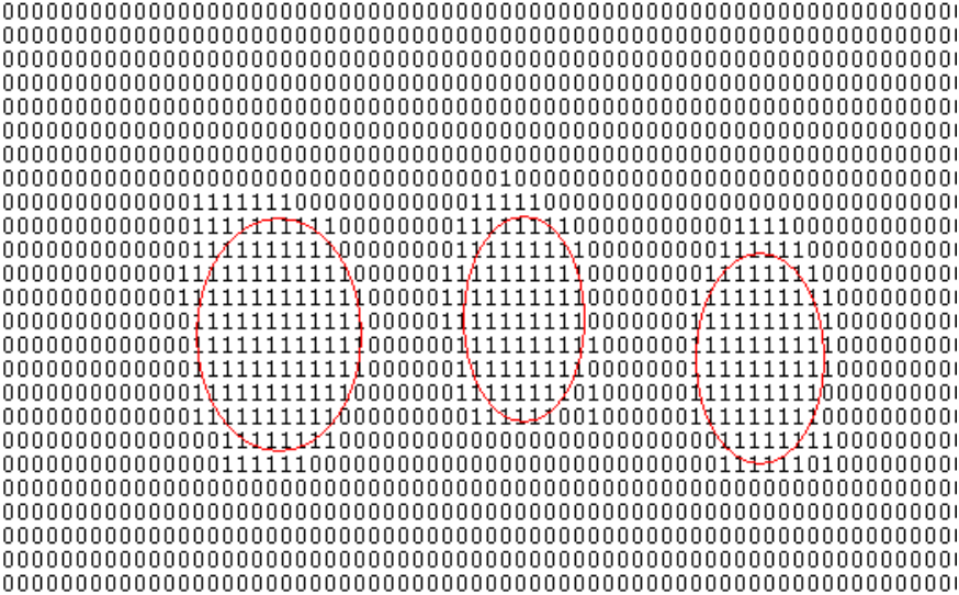
After successful discovery of LEDs, the length, width, average RGB values of ON and OFF states of LED area, for each LED are stored in memory for detecting the ON/OFF state of LEDs in subsequent BitFrames. Successfully discovered LEDs are clustered according to a threshold value of proximity among themselves, for identifying the displays of different sensor nodes.
After successful detection of all sensor nodes, the data LEDs of each sensor node are sorted according to the left-to-right and top-to-bottom ordering of coordinates. Now SAS data for each sensor node is extracted from the BitFrames by comparing the average RGB values of LEDs with previously saved (from All-OFF and All-ON frames) OFF and ON state RGB values of LEDs. For each extracted SAS, the sink matches it with its own computed list of “free” SAS values. If there is a match, the sink marks the corresponding computed SAS as “used” and the sensor node as “SAS Matched”. If extracted SAS of a sensor node does not match with any free SAS values, the corresponding sensor node and all sensor nodes having the same SAS are marked as “SAS Mismatched”. Each BitFrame is then examined: the Sync LEDs of all sensor nodes should be in the OFF state, except for the last frame, where the Sync LED should be in the ON state and all data LEDs of all sensor nodes should be in the OFF state. If this is not the case, it implies that a synchronization error occurred.
If for a sensor node, both “SAS Matched” and “Sync Matched” are true, the sink accepts the sensor node as a “passed”; otherwise, it rejects the sensor node as a “failed” due to mismatch of SAS and/or synchronization errors. The LEDs of a passed sensor node are marked with a rectangle of green color; and the LEDs of a failed sensor node are crossed out with red color (Figure 8). Additionally, an automatic printing of the result-screen is done by the printer connected to the sink. By observing the graphical result on screen of the sink and/or the printed result, the administrator discards the failed sensor nodes.
V Experiments and Results
V-A Experimental Setup
To test our simulator implementing the sensor node initialization method, we used the following set-up. The sink is running on a DELL Vostro 1500 Laptop (1.6 GHz CPU, 2GB RAM, WinXP Pro SP2) connected with a USB Web Camera (Microsoft LifeCam VX6000, up to 30 frames/sec, live video streaming of resolution pixels) and a wireless printer. The webcam can be replaced with any similar camera with a frame rate 30 fps or higher, without any modification to the existing simulator. The camera is set in NON_STOP video capturing mode and frames are taken setting the camera in preview mode. Camera controller is added to the simulator to allow adjusting the focus, tilt and pan of camera as needed.
The transmitting side of the simulator runs on a DELL desktop computer (1.8 GHz CPU, 1 GB RAM, WinXP Pro SP2) connected with LEDs on breadboard (Figure 7) through parallel port (DB25 Connector). The laptop and the desktop computer are connected with our university’s wireless connection (54 Mbps). Figure 7 has a snapshot of our set-up.
V-B Usability Testing
In order to test how our method fares with non-expert users, and especially to figure out if the users are easily and correctly able to discard the failed sensor nodes based on the result screen (and/or print-out), we performed a usability study.
Testing Framework. For creating an automated testing framework, we extended the transmitter application running on the desktop computer by implementing the usability testing and user feedback collection functionality on it. The sink application running on the laptop was configured to send the result (indicating passed or failed sensor nodes) to the desktop application, as soon as it was determined. As there is no interface on breadboard using which the users can turn off the failed sensor node(s), we simulated the “turning off” mechanism in the desktop application. As soon as the desktop application receives the result from the laptop application, it shows the layout of the sensor node field (i.e., the breadboard) on screen, associating each sensor node with a transparent button with the layout of the sensor node in the background. The users are instructed to transfer the result from the laptop screen to the desktop screen by clicking on the buttons (on the desktop screen) corresponding to the failed sensor nodes shown on the laptop screen. After test completion, the desktop application has the functionality of showing the questionnaires to obtain user feedback and logging the data. In our current tests, we did not make use of the printed output.
Test Cases. We created five categories of test cases to evaluate our method against different types of possible attacks and errors. These included (1) matching SAS and no synchronization errors (to simulate normal execution scenarios, where no attacks or faults occur), (2) (single- and multiple-bit) SAS mismatch on a varying number of sensor nodes; (3) missing, pre-mature and delayed turning on of the Sync LED (to simulate synchronization errors), (4) both SAS mismatch and synchronization errors, and (5) variable distance (from 0.5 to 2 feet) between the camera and the transmitters. Ten test cases for each category were created. Each user executed a total of five test cases, one each selected randomly from each of the five categories.
A (portion of the) screenshot of the result of execution of one of the test cases is shown in Figure 8.

Test Participants. We recruited 21 subjects for our usability testing. Subjects were chosen on a first-come first-serve basis from respondents to recruiting posters and email ads. At the end of the tests, the participants were asked to fill out an on screen questionnaire through which we obtained user demographics and their feedback on the method tested.
Recruited subjects were mostly university students, both graduate and undergraduate, with CS and non-CS backgrounds. This resulted in a fairly young (ages between 22-31 [mean=, se=]), well-educated participant group. All participants were regular computer users. 19 out of 21 participants reported they have previously used a PC camera (for internet chat). None of the study participants reported any physical impairments that could have interfered with their ability to complete given task. The gender split was: 17 males and 4 females.
Testing Process. Our study was conducted in a graduate student laboratory of our university. Each participant was given a brief overview of our study goals and our experimental set-up. Each participating user was then asked to follow on-screen instructions on the laptop and desktop computer. No training of any sort was given. Basically, the participants played the role of the administrator in the sensor node initialization method, as depicted in Figure 2. Sink output, user interactions throughout the tests and timings were logged automatically by the testing framework.
After completing the deputed test cases in the above manner, the participants were asked to give some qualitative feedback on how easy or hard they found to focus the camera on all LEDs, to read the result of the output screen and about the overall ease/difficulty of the method. Participants demographic information such as age, gender, educational qualification, visual disability, computer and camera experience is also collected through this questionnaire. All user data and feedback was logged by the testing framework for future analysis.
Test Results. Each of our 21 subjects executed 5 test cases, leading to a total of 105 test cases. Most of the test cases executed successfully giving expected results. In some cases, however, we observed a few errors, which we categorize and describe below.
1. Camera Adjustment Error: We configured our usability testing application in such manner that if all the LEDs are not within the camera viewpoint, an error message is shown to the user asking him/her to re-execute. In our tests, 2 users failed to adjust the camera on one occasion each and thus they had to repeat the tests. Therefore, the rate of camera adjustment error equals of test cases.
2. Sink Mis-reading Error: Sometimes the sink is not able to correctly read the SAS string(s) transmitted by one or more sensor nodes. This could happen when the camera is too distant ( 2 feet) from the sensor nodes or due to reflection of LED light on the table and other nearby surfaces. In our tests, this type of error occurred for a total of 7 sensor nodes, where SAS strings of 1 or 2 sensor nodes were mis-read in some 5 test cases. In 105 tes tcases, the sink dealt with a total of sensor nodes on breadboard and out of them 7 sensor nodes failed due to sink errors. So, rate of sink mis-reading error equals . Note that all of these errors were only false positives, i.e., the mistakenly marked a passed sensor node as a failed one.
3. User Error: A user error occurs when the user is not able to correctly transfer the result, from the laptop screen to the desktop screen (simulating switching off of the failed sensor node). In our tests, 3 users accidentally clicked, on one occasion each, a passed sensor node on the desktop screen (this implies that a passed sensor node was turned off). However, it is important to note that on no occasions did a user miss clicking on a failed sensor node. In other words, we did get a few false positives but no false negatives whatsoever. Thus, rate of user errors from our tests turned out to be equal to .
The average time taken by each user (over the 5 test cases), to complete Steps 2 to 4 of Figure 2, is depicted in Figure 9. As we see, the time taken by all of our users to perform a test is less than a minute [mean= seconds, se=]. Note that these numbers arise when we assume a fairly conservative setting, one where both normal scenarios and attacks or faults occur with equal likelihood. However, in practice, attacks or faults are less likely. Therefore, considering only the normal test case, we find that that on an average a user only takes seconds [se=] to complete the whole process.

The results we obtained through the user feedback questionnaire are shown in Table I. Clearly, most users found the method robust and quite easy to work with.
| Easiness | Very Easy | Easy | Medium Difficult | Difficult | Very Difficult | Impossible |
|---|---|---|---|---|---|---|
| Camera Adjustment to LEDs | 5 | 13 | 3 | 0 | 0 | 0 |
| Detection of Failed Sensor Nodes | 11 | 10 | 0 | 0 | 0 | 0 |
| Easiness of Mechanism | 7 | 10 | 4 | 0 | 0 | 0 |
VI Discussion and Conclusion
We proposed a novel method for secure initialization of sensor nodes. Based on our testing with the method, we make the following conclusions.
Efficiency: Using N Data LEDs and one Sync LED per sensor node, the transmission requires ms. This is equal to 3.25 sec for N=2 and 20-bit SAS data. Extraction of SAS data from captured frames and displaying the result on screen require less than 3-4 seconds. So, execution time of the method is 7-8 seconds. Overall, as our experiment results show, most users took less than a minute to perform the whole process. Also, as shown in [15], most existing commercial sensor motes (e.g. Mica2) can efficiently execute (within a minute) the public key operations (private and public key generation, and one exponentiation). Note that these operations constitute the dominant costs in the SAS protocol (of Figure 1) that a sensor node executes with the sink. The sink, on the other hand, is assumed to be a computer with a fairly strong computational power and therefore can efficiently execute parallel protocol instances with each of the sensor nodes.66 6 The protocol of Figure 1 works with sink’s permanent public/private keys.
Based on the above numbers, we recommend setting minutes, as the time period (to complete Steps 2 to 4 of Figure 2) by which the key initialization will be accepted by each sensor node, by default. As our experiments show, within 2 minutes, a human user can safely complete the initialization process, turning off any (failed) sensor nodes, if necessary.
Power Requirements: From [15], we know that most available commercial sensor motes can do public key crypto operations using only a small amount of power. Now, we show that the SAS data transmission through blinking LEDs also incurs a minimal overhead on sensor motes in terms of power. For 20-bit SAS data transmission, the three LEDs on each sensor mote light-up 13 times (for a period of 250ms), i.e., for a duration of =seconds. Each LED has a drop voltage, = Volts (typical range 1.7-3.3 Volts); Current Rating, = mA (typical range 2-3 mA). Therefore, the maximum energy consumption per sensor mote (3 LEDs), E== Volt-A-seconds = Joules. As stated in [15], the Energizer No. E91, two AA batteries used in Mica2 motes, have a total energy of = Joules. So, our SAS data transmission requires of battery life of Mica2. As shown in [15], public key generation requires 0.816 Joules of energy. Thus, our SAS data transmission is more that 13.11 times better than the public key generation in terms of power consumption
Robustness: Our method is quite robust to varying distances between the transmitter and receiver. The distance between the camera and sensor motes on breadboard can be up to 2 feet. The method also works quite well in varying lighting and brightness conditions as it deterministically learns the environment using the first two, All-OFF and All-ON, frames in each session. The method could fail in presence of background noise during transmission and reception of SAS data. It will not work in blackout or blackout in the middle of transmission. Huge variations of lighting conditions during transmission of SAS data which exceed color threshold of LEDs or shaking/displacement of all sensor motes/camera while transmission of SAS data exceeding the dimension threshold of LEDs will also cause failure of the method. However, these will only lead to false positives and not to an attack. Except for the camera adjustment errors (as discussed in Section V-B), all errors occurring with our method are localized i.e, if a single sensor mote fails due to some reason, only that particular sensor node needs to be re-initialized. Note that this is unlike the MiB scheme of [11], where any errors lead to the re-initialization/re-keying of the whole batch of sensor motes. Even when camera adjustment occur in our method, only the SAS data transmission needs be repeated, not the whole initialization process. On the other hand, MiB is less prone to user errors than our method. However, our results indicate that our user errors only lead to false positives and are negligible nevertheless. In our future work, we plan to explore how default rejection (as opposed to our current default acceptance mechanism) would impact the efficiency, usability and scalability of our method. It will clearly improve security.
Scalability: Our method can be used to to initialize multiple sensor nodes per batch. We tested the method with 16 sensor nodes having three LEDs each. By using good quality wide-angle cameras (which will somewhat increase the overall cost of the system), this number can be greatly improved, we believe. We are currently exploring ways to make our method more scalable. Note that increase in the number of sensor nodes will come at only a slight cost of increase in the length of SAS data. For example, to support 128 sensor nodes, we would need to transmit 22 SAS bits.
Usability: Via a systematic usability study, we find that our method is quite user friendly. It does not require any expertise or prior training. Little or no acquaintance with the method is enough to administer the process. It is easy to work with and enables easy detection of failed sensor nodes by observing the result on the screen of the sink. Unlike the MiB scheme of [11], the administrator does not have to deal with a specialized and often cumbersome Faraday Cage. Of course, the administrator has to deal with a camera in our method, however, most users are getting more and more familiar with cameras as they become ubiquitous. Moreover, a camera can be used for purposes other than key distribution and is thus not truly specialized. Also note that the sensor motes per batch do not need to be homogeneous. They can have different number, color of LEDs, in any topology whatsoever (the only requirement being they all possess one RED colored LED to act as the Sync LED). Recall that this is unlike MiB [11], which can only support homogeneous sensor motes with very similar weights. We consider this as an important issue with respect to usability – an administrator might need to initialize a diverse pool of sensor motes and should not need to group them up.
Simplicity and Economic Viability: The sink needs only a camera and each sensor nodes require at least two LEDs (one Sync and one Data) which are very cheap and commonly available. In fact, most existing commercial sensor motes have three LEDs. Our method is quite economic, as opposed to MiB [11] which requires a specialized Faraday Cage and an additional sensor mote (called “keying devices”) having USB interfaces.
Resistance to Malicious Sensor Nodes: Our method offers a natural protection against corrupted or malicious sensor nodes77 7 A manufacturer could possibly sneak in malicious sensor node(s) along with normal sensor nodes shipped to a customer, as pointed out in [11].. Our method is based on an authenticated key exchange protocol following the security model of [28]. This model guarantees that an adversary who learns session key(s) corresponding to some corrupted session(s), does not learn any information about the keys corresponding to other uncorrupted sessions. This is unlike MiB [11], where a single corrupted sensor node can compromise keys corresponding to all other sensor nodes88 8 [11] suggests using a software-based attestation technique [33] to prevent this attack..
References
- [1] A. Perrig, R. Szewczyk, V. Wen, D. E. Culler, and J. D. Tygar, “Spins: security protocols for sensor netowrks,” in MOBICOM, 2001.
- [2] L. Eschenauer and V. D. Gligor, “A key-management scheme for distributed sensor networks,” in ACM CCS, 2002.
- [3] D. Liu and P. Ning, “Establishing pairwise keys in distributed sensor networks,” in ACM CCS, 2003.
- [4] W. Du, J. Deng, Y. S. Han, and P. K. Varshney, “A pairwise key pre-distribution scheme for wireless sensor networks,” in ACM CCS, 2003.
- [5] H. Chan, A. Perrig, and D. X. Song, “Random key predistribution schemes for sensor networks,” in IEEE S&P, 2003.
- [6] A. Perrig, J. Stankovic, and D. Wagner, “Security in wireless sensor networks,” ACM Commun., vol. 47, pp. 53–57, 2004.
- [7] F. Hu and N. Sharma, “Security considerations in ad hoc sensor networks,” Ad Hoc Networks, vol. 3, 2005.
- [8] W. Du, J. Deng, Y. Han, S. Chen, and P. Varshney, “A key management scheme for wireless sensor networks using deployment knowledge,” in IEEE INFOCOM’04, March 2004.
- [9] C. Karlof, N. Sastry, and D. Wagner, “Tinysec: a link layer security architecture for wireless sensor networks,” in SenSys, 2004.
- [10] D. Balfanz, D. Smetters, P. Stewart, and H. C. Wong, “Talking to strangers: Authentication in ad-hoc wireless networks,” in NDSS, 2002.
- [11] K. Cynthia, M. Luk, R. Negi, and A. Perrig, “Message-in-a-bottle: User-friendly and secure key deployment for sensor nodes,” in ACM SenSys, 2007.
- [12] J. M. McCune, A. Perrig, and M. K. Reiter, “Seeing-is-believing: Using camera phones for human-verifiable authentication,” in IEEE S&P, 2005.
- [13] M. T. Goodrich, M. Sirivianos, J. Solis, G. Tsudik, and E. Uzun, “Loud and Clear: Human-Verifiable Authentication Based on Audio,” in ICDCS, 2006.
- [14] N. Saxena, J.-E. Ekberg, K. Kostiainen, and N. Asokan, “Secure device pairing based on a visual channel,” in IEEE S&P, short paper, 2006.
- [15] D. J. Malan, M. Welsh, and M. D. Smith, “A public-key infrastructure for key distribution in tinyos based on elliptic curve cryptography,” in SECON, 2004.
- [16] C. Castelluccia and P. Mutaf, “Shake them up!: a movement-based pairing protocol for cpu-constrained devices,” in MobiSys.
- [17] K. B. Rasmussen and S. Capkun, “Implications of radio fingerprinting on the security of sensor networks,” in IEEE SecureComm, 2007.
- [18] L. E. Holmquist, F. Mattern, B. Schiele, P. Alahuhta, M. Beigl, and H.-W. Gellersen, “Smart-its friends: A technique for users to easily establish connections between smart artefacts,” 2001.
- [19] J. Lester, B. Hannaford, and G. Borriello, “”are you with me?” - using accelerometers to determine if two devices are carried by the same person,” in Pervasive, 2004.
- [20] F. Stajano and R. J. Anderson, “The resurrecting duckling: Security issues for ad-hoc wireless networks.” in Security Protocols Workshop, 1999.
- [21] S. Pasini and S. Vaudenay, “SAS-Based Authenticated Key Agreement,” in PKC, 2006.
- [22] S. Laur, N. Asokan, and K. Nyberg, “Efficient mutual data authentication based on short authenticated strings,” ePrint Archive, 2005.
- [23] C. Soriente, G. Tsudik, and E. Uzun, “HAPADEP: Human Asisted Pure Audio Device Pairing,” in eprint Archive, 2007.
- [24] E. Uzun, K. Karvonen, and N. Asokan, “Usability analysis of secure pairing methods,” in USEC, 2007.
- [25] C. Soriente, G. Tsudik, and E. Uzun, “BEDA: Button-Enabled Device Association,” in IWSSI, 2007.
- [26] R. Prasad and N. Saxena, “Efficient device pairing using human-comparable audiovisual patterns,” in ACNS, 2008.
- [27] S. Vaudenay, “Secure communications over insecure channels based on short authenticated strings,” in CRYPTO, 2005.
- [28] R. Canetti and H. Krawczyk, “Analysis of key-exchange protocols and their use for building secure channels.” in EUROCRYPT, 2001.
- [29] H. A. Rowley, S. Baluja, and T. Kanade, “Neural network-based face detection,” in Pattern Analysis and Machine Intelligence(PAMI), 1998.
- [30] H. Schneiderman and T. Kanade, “A statistical method for 3d object detection applied to faces and cars,” in TRINITY, 2003.
- [31] P. Viola and M. Jones, “Rapid object detection using a boosted cascade of simple features,” in Computer Vision and Pattern Recognition, 2001.
- [32] J. Weszka, “A survey of threshold selection techniques,” in Computer Graphics and Image Processing. Vol. 7, 1978.
- [33] A. Seshadri, A. Perrig, L. van Doorn, and P. K. Khosla, “Swatt: Software-based attestation for embedded devices,” in IEEE S&P, 2004.