Evidence for reversible control of magnetization in a ferromagnetic material via spin-orbit magnetic field
Conventional computer electronics creates a dichotomy between how information is processed and how it is stored. Silicon chips process information by controlling the flow of charge through a network of logic gates. This information is then stored, most commonly, by encoding it in the orientation of magnetic domains of a computer hard disk. The key obstacle to a more intimate integration of magnetic materials into devices and circuit processing information is a lack of efficient means to control their magnetization. This is usually achieved with an external magnetic field or by the injection of spin-polarized currents [1, 2, 3]. The latter can be significantly enhanced in materials whose ferromagnetic properties are mediated by charge carriers [4]. Among these materials, conductors lacking spatial inversion symmetry couple charge currents to spin by intrinsic spin-orbit (SO) interactions, inducing nonequilibrium spin polarization [5, 6, 7, 8, 9, 10, 11] tunable by local electric fields. Here we show that magnetization of a ferromagnet can be reversibly manipulated by the SO-induced polarization of carrier spins generated by unpolarized currents. Specifically, we demonstrate domain rotation and hysteretic switching of magnetization between two orthogonal easy axes in a model ferromagnetic semiconductor.
In crystalline materials with inversion asymmetry, intrinsic spin-orbit interactions (SO) couple the electron spin with its momentum . The coupling is given by the Hamiltonian , where is the Planck’s constant and is the electron spin operator (for holes should be replaced by the total angular momentum ). Electron states with different sign of the spin projection on are split in energy, analogous to the Zeeman splitting in an external magnetic field. In zinc-blende crystals such as GaAs there is a cubic Dresselhaus term[12] , while strain introduces a term that is linear in , where is the difference between strain in the and directions[13]. In wurzite crystals or in multilayered materials with structural inversion asymmetry there also exists the Rashba term[14] which has a different symmetry with respect to the direction of , , where is along the axis of reduced symmetry. In the presence of an electric field the electrons acquire an average momentum, which leads to the generation of an electric current in the conductor, where is the resistivity tensor. This current defines the preferential axis for spin precession . As a result, a nonequilibrium current-induced spin polarization is generated, whose magnitude depends on the strength of various mechanisms of momentum scattering and spin relaxation[5, 15]. This spin polarization has been measured in non-magnetic semiconductors using optical[7, 8, 9, 16, 11] and electron spin resonance[17] techniques. It is convenient to parameterize in terms of an effective magnetic field . Different contributions to have different current dependencies (), as well as different symmetries with respect to the direction of , as schematically shown in Fig. 1(c,d), allowing one to distinguish between spin polarizations in different fields.
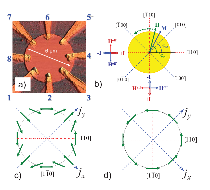

In order to investigate interactions between the SO-generated magnetic field and magnetic domains we have chosen (Ga,Mn)As, a p-type ferromagnetic semiconductor[18, 19] with zinc blende crystalline structure similar to GaAs. Ferromagnetic interactions in this material are carrier-mediated[20, 21]. The total angular momentum of the holes couples to the magnetic moment of Mn ions via antiferromagnetic exchange . This interaction leads to the ferromagnetic alignment of magnetic moments of Mn ions and equilibrium polarization of hole spins. If additional, non-equilibrium spin polarization of the holes is induced, the interaction of the hole spins with magnetic moments of Mn ions allows one to control ferromagnetism by manipulating . Magnetic properties of (Ga,Mn)As are thus tightly related to the electronic properties of GaAs. For example, strain-induced spin anisotropy of the hole energy dispersion is largely responsible for the magnetic anisotropy in this material. (Ga,Mn)As, epitaxially grown on (001) surface of GaAs, is compressively strained, which results in magnetization lying in the plane of the layer perpendicular to the growth direction, with two easy axes along the [100] and [010] crystallographic directions[22, 23]. Recently, control of magnetization via strain modulation has been demonstrated[24]. In this paper we use SO-generated polarization to manipulate ferromagnetism.
We report measurements on two samples fabricated from (Ga,Mn)As wafers with different Mn concentrations. The devices were patterned into circular islands with 8 non-magnetic Ohmic contacts, as shown in Fig. 1a and discussed in Methods. In the presence of a strong external magnetic field , the magnetization of the ferromagnetic island is aligned with the field. For weak fields, however, the direction of magnetization is primarily determined by magnetic anisotropy. As a small field ( mT) is rotated in the plane of the sample, the magnetization is re-aligned along the easy axis closest to the field direction. Such rotation of magnetization by an external field is demonstrated in Fig. 2. For the current , the measured is positive for and negative for . Note that , and thus also the magnetization, switches direction when the direction of is close to the hard axes [110] and , confirming the cubic magnetic anisotropy of our samples. The switching angles where changes sign are denoted as on the plot.
In the presence of both external and SO fields, we expect to see a combined effect of on the direction of magnetization. For small currents (few A) , and does not depend on the sign or the direction of the current. At large dc currents the value of becomes current-dependent and we define . Specifically, for the switching of magnetization occurs for mA at smaller than for mA, . For the magnetization switching, the -dependence of switching angle is reversed, . There is no measurable difference in switching angle for the and transitions (). When the current is rotated by 90∘ (), we observe , , and . In Fig. 2(c) we show that decreases as current decreases and drops below experimental resolution of at A. Similar data is obtained for Sample B, see Fig. S4 in Supplementary Information.
The data can be qualitatively understood if we consider an additional current-induced effective magnetic field , as shown schematically in Fig. 1b. When an external field aligns the magnetization along one of the hard axes, a small perpendicular field can initiate magnetization switching. For , the effective field aids the magnetization switching, while it hinders the switching. For and , where and magnetization transitions occur, does not affect the transition angle, . For the direction of the field is reversed relative to the direction of the current, compared to the case. The symmetry of the measured with respect to coincides with the unique symmetry of the strain-related SO field, Fig. 1(c).
The dependence of on various magnetic fields and current orientations is summarized in Fig. 3(a,b). Assuming that the angle of magnetization switching depends only on the total field , we can extract the magnitude and angle from the measured , thus reconstructing the whole vector . Following a geometrical construction depicted in Fig. 3d and taking into account that is small, we find that
and can be found from the comparison of switching at two angles. We find that , or for and . In order to further test our procedure we performed similar experiments with small current A but constant additional magnetic field playing the role of . The measured coincides with the applied within the precision of our measurements. (see Fig. S5 of Supplementary Information).


In Fig. 3(c), is plotted as a function of the average current density for both samples. There is a small difference in the vs dependence for and . The difference can be explained by considering the current-induced Oersted field in the metal contacts. The Oersted field is localized under the pads, which constitutes only 7% (2.5%) of the total area for samples A (B). The Oersted field has the symmetry of the field depicted in Fig. 1(d), and is added to or subtracted from the SO field, depending on the current direction. Thus, for and for . We estimate the fields to be as high as 0.6 mT under the contacts at mA, which corresponds to mT (0.015 mT) averaged over the sample area for samples A (B). These estimates are reasonably consistent with the measured values of 0.07 mT (0.03 mT). Finally, we determine as an average of between the two current directions. The SO field depends linearly on , as expected for strain-related SO interactions: and T cm2/A for samples A and B respectively.
We now compare the experimentally measured with theoretically calculated effective SO field. In (Ga,Mn)As, the only term allowed by symmetry that generates linear in the electric current is the term, which results in the directional dependence of on precisely as observed in experiment. As for the magnitude of , for three-dimensional holes we obtain
where is the electric field, is the Luttinger Landé factor for holes, is the Bohr magneton, and and are densities and lifetimes for the heavy (h) and light (l) holes. Detailed derivation of is given in Supplementary Information. Using this result, we estimate T cm2/A assuming and , where is the resistivity measured experimentally, and using , cm-3. The agreement between theory and experiment is excellent. It is important to note, though, that we used GaAs band parameters[25] , where is the free electron mass, and eVÅ. While the corresponding parameters for (Ga,Mn)As are not known, the use of GaAs parameters appears reasonable. We note, for example, that GaAs parameters adequately described tunnelling anisotropic magnetoresistance in recent experiments[26].
Finally, we demonstrate that the current-induced effective SO field is sufficient to reversibly manipulate the direction of magnetization. In Fig. 4a we plot the -dependence of for Sample A, showing the magnetization switching. If we fix mT at , forms a hysteresis loop as current is swept between mA. is changing between , indicating that is switching between and directions. Short (100 msec) 1 mA current pulses of alternating polarity are sufficient to permanently rotate the direction of magnetization. The device thus performs as a non-volatile memory cell, with two states encoded in the magnetization direction, the direction being controlled by the unpolarized current passing through the device. The device can be potentially operated as a 4-state memory cell if both and directions can be used to inject current. We find that we can reversibly switch the magnetization with currents as low as 0.5 mA (current densities A/cm2), an order of magnitude smaller than by polarized current injection in ferromagnetic metals[1, 2, 3], and just a few times larger than by externally polarized current injection in ferromagnetic semiconductors[4].
Methods
The (Ga,Mn)As wafers were grown by molecular beam epitaxy at 265 ∘C and subsequently annealed at 280 ∘C for 1 hour in nitrogen atmosphere. Sample A was fabricated from 15-nm thick epilayer with 6%Mn, and Sample B from 10-nm epilayer with 7% Mn. Both wafers have Curie temperature K. The devices were patterned into 6 and 10 m-diameter circular islands in order to decrease domain pinning. Cr/Zn/Au (5nm/10nm/300nm) Ohmic contacts were thermally evaporated. All measurements were performed in a variable temperature cryostat at K for Sample A and at 25 K for Sample B, well below the temperature of (Ga,Mn)As-specific cubic-to-uniaxial magnetic anisotropy transitions[27], which has been measured to be at 60 K and 50 K for the two wafers. Temperature rise for the largest currents used in the reported experiments was measured to be K.
Transverse anisotropic magnetoresistance is measured using the four-probe technique, which insures that possible interfacial resistances, e.g., those related to the antiferromagnetic ordering in the Cr wetting layer[28], do not contribute to the measured . The DC current was applied either along [110] (contacts 4-8 in Fig. 1a) or along (contacts 2-6) direction. Transverse voltage was measured in the Hall configuration, e.g., between contacts 2-6 for . To ensure uniform magnetization of the island, magnetic field was ramped to 0.5 T after adjusting of the current at the beginning of each field rotation scan. We monitor between different contact sets (e.g. 1-7, 4-6 and 3-5) to confirm the uniformity of magnetization within the island.
In order to determine the direction of magnetization , we use the dependence of on magnetization[29]:
where , are the resistivities for magnetization oriented parallel and perpendicular to the current, and is an angle between magnetization and current. In a circular sample the current distribution is non-uniform and the angle between the magnetization and the local current density varies throughout the sample. However, the resulting transverse AMR depends only on . For the current-to-current-density conversion, we model our sample as a perfect disc with two point contacts across the diameter. The average current density in the direction of current injection is , where is the disk radius and is the (Ga,Mn)As layer thickness. In a real sample the length of contact overlap with (Ga,Mn)As insures that changes by less than factor of 3 throughout the sample. A detailed discussion of the current distribution and of measurements of Joule heating can be found in Supplementary Information.
References
- [1] Slonczewski, J. C. J. Magn. Magn. Mater. 159, 1 – 7 (1996).
- [2] Berger, L. Phys. Rev. B 54(13), 9353 – 8 (1996).
- [3] Myers, E. B., Ralph, D. C., Katine, J. A., Louie, R. N., and Buhrman, R. A. Science 285, 867 – 70 (1999).
- [4] Chiba, D., Sato, Y., Kita, T., Matsukura, F., and Ohno, H. Phys. Rev. Lett. 93(21), 216602 (2004).
- [5] Aronov, A. G. and Lyanda-Geller, Y. B. JETP Lett. 50, 431 – 4 (1989).
- [6] Edelstein, V. M. Solid State Commun. 73, 233 – 5 (1990).
- [7] Kalevich, V. K. and Korenev, V. L. JETP Lett. 52, 230 – 5 (1990).
- [8] Kato, Y., Myers, R. C., Gossard, A. C., and Awschalom, D. D. Nature 427, 50–53 (2004).
- [9] Silov, A. Y., Blajnov, P. A., Wolter, J. H., Hey, R., Ploog, K. H., and Averkiev, N. S. Appl. Phys. Lett. 85, 5929–5931 (2004).
- [10] Ganichev, S. D. Int. J of Mod. Phys. B 22(1-2), 1–26 (2008).
- [11] Meier, L., Salis, G., Shorubalko, I., Gini, E., Schoen, S., and Ensslin, K. Nat. Phys. 3, 650–654 (2007).
- [12] Dresselhaus, G. Phys. Rev. 100, 580 – 586 (1955).
- [13] Bir, G. L. and Pikus, G. E. Symmetry and strain-induced effects in semiconductors. Wiley, New York, (1974).
- [14] Bychkov, Y. A. and Rashba, E. I. J. Phys. C: Solid State Phys. 17, 6039–6045 (1984).
- [15] Aronov, A. G., Lyanda-Geller, Y. B., and Pikus, G. E. Sov. Phys. JETP 73, 537 – 41 (1991).
- [16] Golub, L. E., Ganichev, S. D., Danilov, S. N., Schneider, P., Bel’kov, V. V., Wegscheider, W., Weiss, D., and Prettl, W. J. Magn. Magn. Mater. 300, 127 – 31 (2006).
- [17] Wilamowski, Z., Malissa, H., Schaffler, F., and Jantsch, W. Phys. Rev. Lett. 98, 187203 (2007).
- [18] Ohno, H., Shen, A., Matsukura, F., Oiwa, A., Endo, A., Katsumoto, S., and Iye, Y. Appl. Phys. Lett. 69, 363 – 5 (1996).
- [19] Ohno, H. Science 281, 951 – 6 (1998).
- [20] Dietl, T., Ohno, H., Matsukura, F., Cibert, J., and Ferrand, D. Science 287, 1019 – 22 (2000).
- [21] Berciu, M. and Bhatt, R. N. Phys. Rev. Lett. 87, 107203 (2001).
- [22] Welp, U., Vlasko-Vlasov, V. K., Liu, X., Furdyna, J. K., and Wojtowicz, T. Phys. Rev. Lett. 90, 167206 (2003).
- [23] Liu, X., Sasaki, Y., and Furdyna, J. K. Phys. Rev. B 67, 205204 (2003).
- [24] Overby, M., Chernyshov, A., Rokhinson, L. P., Liu, X., and Furdyna, J. K. Appl. Phys. Lett. 92, 192501 (2008).
- [25] Chantis, A. N., Cardona, M., Christensen, N. E., Smith, D. L., van Schilfgaarde, M., Kotani, T., Svane, A., and Albers, R. C. Pys. Rev. B 78(7), 075208 AUG (2008).
- [26] Elsen, M., Jaffres, H., Mattana, R., Tran, M., George, J.-M., Miard, A., and Lemaitre, A. Phys. Rev. Lett. 99(12), 127203 SEP 21 (2007).
- [27] Chiba, D., Sawicki, M., Nishitani, Y., Nakatani, Y., Matsukura, F., and Ohno, H. Nature 455, 515–518 (2008).
- [28] Smit, P. and Alberts, H. L. J. Appl. Phys. 63(8), 3609–10 (1988).
- [29] Tang, H. X., Kawakami, R. K., Awschalom, D. D., and Roukes, M. L. Phys. Rev. Lett. 90, 107201 (2003).
- [30] Rokhinson, L. P., Lyanda-Geller, Y., Ge, Z., Shen, S., Liu, X., Dobrowolska, M., and Furdyna, J. K. Phys. Rev. B 76, 161201 (2007).
Supplementary Information
Evidence for the reversible control of magnetization in a ferromagnetic material via spin-orbit magnetic field
A. Chernyshov, M. Overby, X. Liu, J. K. Furdyna, Y. Lyanda-Geller, and L.
P. Rokhinson
I Joule heating
(Ga,Mn)As is a magnetic semiconductor with strong temperature dependence of resistivity, see Fig. 5(a). The enhancement of resistivity at 80 K is due to the enhancement of spin scattering in the vicinity of the Curie temperature . Inelastic scattering length in these materials is just a few tenths of nm, and we expect holes to be in thermal equilibrium with the lattice[30]. Thus resistivity can be used to measure the temperature of the sample.

In Fig. 5(b,c) we plot temperature and current dependences of the sample resistance in the vicinity of 40 K. This data is combined in (d), where the sample temperature change due to Joule heating is plotted as a function of dc current. The maximum temperature rise does not exceed 3 K at mA in our experiments. This small heating ensures that the sample temperature stays well below the Curie temperature ( K) and the (Ga,Mn)-specific cubic-to-uniaxial magnetic anisotropy transition ( K for sample A and K for sample B) when experiments are performed at 40 K and 25 K for samples A and B, respectively. Observation of different angles for magnetization switching for and (Fig. 2) further confirms that heating is not responsible for the reported effects (Joule heating is and does not depend on the current direction).
II Current distribution in circular samples
Magnetization-dependent scattering in (Ga,Mn)As results in an anisotropic correction to the resistivity tensor which depends on the angle between magnetization and local current density [29]:
| (1) |
where () are the resistivities for (), and we assumed that both and lie within the plane of the sample. The off-diagonal resistivity (transverse anisotropic magnetoresistance) can be non-zero even in the absence of the external magnetic field. The difference and we first calculate the local potential inside the sample by approximating it as a disk of radius and thickness with isotropic resistivity :
| (2) |
where current is injected along the -axis. Current density is plotted in Fig. 6(a). Metal contacts have a radius of m in our samples, which limits the current density near the current injection regions. Integrating over the sample area we find average current density
| (3) |

We find the transverse voltage as a correction to the potential due to the anisotropic resistivity :
| (4) |
The current distribution is non-uniform, and the local electric field depends on the total angle , where and , see Fig. 6(b). This integral can be evaluated analytically, and the transverse anisotropic magnetoresistance (AMR) is found to be the same as for an isotropic current flow, independent of the distance of the voltage contacts from the center of the disk:
| (5) |
The magnetization angle can therefore be directly calculated from the measured transverse resistance .
III Current-generated Oersted magnetic fields
In this section we estimate conventional current-generate magnetic fields in our device that are not related to spin-orbit interactions. There are two contributions to the Oersted magnetic fields: a magnetic field due to non-uniform current distribution within the sample, and a field generated by high currents in the vicinity of the metal contacts.
We can calculate the Oersted field inside (Ga,Mn)As by using the Biot-Savart formula:
| (6) |
where is the permeability of free space, and the integral is taken over the volume of the disk. The most significant normal component of the field is shown in Fig. 3(c). The largest Oe, which is negligible compared to the 2000 Oe anisotropy field that keeps the magnetization in-plane.

The second contribution to the Oersted field originates from contact pads, see Fig. 7. The conductivity of gold contacts is much higher that of (Ga,Mn)As, and the current flows predominantly through the metal within contact regions, thus generating both in-plane () and out-of plane () magnetic fields in (Ga,Mn)As underneath and at the edges of the contact pads. The maximum value of the field can be estimated as , where is the total current and m is the width of the contact pad. This field can be as high as 6 Oe for mA. The field is localized under the pads, which constitute only 1/12th of the sample area.
The field does not induce in-plane magnetization rotation. The field and the effective spin-orbit field have different symmetries with respect to the current rotation, see Fig. 3(b,c), and thus can be experimentally distinguished. The two fields point in the same direction for , but in the opposite direction for the current rotated by , . Experimentally, we observe an effective field which corresponds to the symmetry of the SO effective field. However, there is a small difference in the slopes of vs curves for the two orthogonal current directions, Fig. 3(a,b), because the contact field is added to the SO field for and subtracted from SO field for . Both fields . From the ratio of the slopes () we can calculate the strength of the contact field, . This experimentally found ratio is consistent with the above estimate if we average the contact Oersted field over the sample area.
IV Dependence of transverse anisotropic magnetoresistance on current and field orientation

In order to test the procedure of the effective field mapping, we performed control experiments where a small constant external magnetic field was playing the role of spin-orbit field. In these experiments the current was reduced to A. The results, shown in Fig. 9, are quantitatively similar to the effect of the spin-orbit field.

V Calculation of the effective spin-orbit field induced by the electric current
Manipulation of localized spins, electronic, nuclear or ionic, can be achieved via manipulation of free carrier spins. The free carrier spins can be manipulated by the external magnetic field, by the Oersted magnetic field of the current, and by the electric current via intrinsic spin-orbit interactions. The intrinsic spin-orbit interactions arise in crystalline systems, in which axial vectors, such as spin polarization, and polar vectors, such as the electric current, behave equivalently with respect to the symmetry trasformations of a crystal. The crystal symmetry then allows the transformation of the electric current into a spin polarization of charge carriers. In this work, Mn ions of the ferromagnetic semiconductor (Ga,Mn)As, and thus its ferromagnetic properties, are affected by the electric current via the intrinsic spin-orbit interactions.
In (Ga,Mn)As, charge carriers are holes with an angular momentum . In contrast to electron systems, the hole system is defined by a very strong coupling of the total angular momentum to the hole momentum , which includes both terms quadratic in and independent of . These terms are quadratic in , and they are not present for electrons with spin 1/2. The Luttinger-Pikus Hamiltonian quadratic in is[13]
| (7) |
where . Despite the presence of a very strong spin-orbit coupling, which leads to the spectral splitting of holes into two pairs of states, this Hamiltonian on its own cannot result in a spin polarization of holes induced by the electric current. Terms capable of generating spin polarization in systems characterized by the absence of center of symmetry in the crystal and by a corresponding additional lowering of the crystalline symmetry in the presence of strain, read
| (8) |
where cyclic permutation of indices is implied. The first term is cubic in the hole momentum, and it can lead only to the polarization of hole spins cubic in the electric current (and only when the current direction is away from the high symmetry axes). For effects linear in electric current this term is only relevant insofar as it contributes to the spin relaxation of the holes. The third term contains off-diagonal components of the strain tensor, and is negligible in (Ga,Mn)As crystals under study. In this system, strain originates from doping by Mn ions, and constitutes tension along the growth axis defined by the component and . Thus only the second term results in a current-induced spin polarization. The symmetry of the corresponding effective field, , depends markedly on the crystallographic orientation. When an electric field is applied, the direction of the generated hole spin polarization with respect to the orientation of the electric current is the same as the direction of the SO effective field with respect to the hole momentum. Such peculiar symmetry differs from the symmetry of the Oersted magnetic field, and thus allows one to distinguish between these effects.
We consider now the approximation linear in strain, when only the strain-dependent term proportional to is taken into account, and strain-dependent terms in are omitted. In this case the hole spectrum given by splits into heavy and light hole branches. The mechanism of generation a spin polarization by the effective SO field in the presence of an electric current is simply a shift in the distribution functions for heavy and light holes in momentum space. In contrast low symmetry electron systems[15], where spin polarization is associated entirely with the relaxation of spins, in case of holes the spin relaxation occurs on the time scale of momentum relaxation and plays no role in the current-induced spin polarization. At low temperatures the hole angular momentum density is given by
| (9) |
where correspond to principal axes and , characteristic times are defined by mobilities of holes in the corresponding bands, and are densities of holes in these bands. At room temperatures in the denominator is to be replaced by , being the lattice temperature and the Boltzman constant. Estimates show that the negative term in brackets of Eq. 9 is dominant.
We note that in the case of very strong deformations the spin relaxation of holes occurs on the times scale longer than that of momentum relaxation. Then simple shift of hole distribution functions in momentum space is no longer sufficient for generating spin polarization by current, and the mechanism of the effect becomes analogous to that for electrons[15]. We will present the results for hole spin polarization generated by electric current at arbitrary value of strain elsewhere.
The spin polarization given by Eq. 9 leads to an effective magnetic field acting on the Mn ions. In order to calculate what external magnetic field would result in the same polarization as that generated by the current, we calculate the average spin density induced by an external magnetic field:
| (10) |
The ratio of polarizations and gives the electric field polarization measured in units of magnetic field. We note that while the SO field affects Mn ions only via the exchange interaction, the Oersted or the external magnetic field also acts on the ions directly. However, the magnitude of the exchange interaction, meV is quite large, making the exchange interaction dominant. We will therefore omit the discussion of direct polarization of Mn by external fields.