An Improved Neutron Electric Dipole Moment Experiment
Abstract
A new measurement of the neutron EDM, using Ramsey’s method of separated oscillatory fields, is in preparation at the new high intensity source of ultra-cold neutrons (UCN) at the Paul Scherrer Institute, Villigen, Switzerland (PSI). The existence of a non-zero nEDM would violate both parity and time reversal symmetry and, given the CPT theorem, might lead to a discovery of new CP violating mechanisms. Already the current upper limit for the nEDM ( cm) constrains some extensions of the Standard Model.
The new experiment aims at a two orders of magnitude reduction of the experimental uncertainty, to be achieved mainly by (1) the higher UCN flux provided by the new PSI source, (2) better magnetic field control with improved magnetometry and (3) a double chamber configuration with opposite electric field directions.
The first stage of the experiment will use an upgrade of the RAL/Sussex/ILL group’s apparatus (which has produced the current best result) moved from Institut Laue-Langevin to PSI. The final accuracy will be achieved in a further step with a new spectrometer, presently in the design phase.
I Motivation
Although all experiments conducted so far measured a value consistent with zero, there are still reasons to suspect that the neutron has an electric dipole moment significantly larger than cm [1], predicted by the Standard Model (SM).
In general, the existence of particles with an EDM would violate both parity () and time reversal symmetries (). Invoking invariance this is equivalent to a violation of invariance, as discovered e.g. in the K0 and B0 systems. Additional unknown sources of violation are of much interest as a possible explanation of one of the biggest puzzles in modern physics, namely, the almost 9 orders of magnitude large discrepancy between the observed Baryon Asymmetry of the Universe (BAU) and the one predicted by the SM and the Big Bang theory. violation is introduced with the phase in the Cabibbo-Kobayashi-Maskawa (CKM) mixing matrix and tuned such that it explains the symmetry breaking observed in the K0 and B0 sectors.
As suggested by Sakharov [2], the missing BAU could dynamically arise from an initial state with baryon number equal zero if the following conditions hold: (i) baryon number non-conservation, (ii) the existence of both and violating processes (iii) occurring in a non-equilibrium state at an early epoch in the Universe. The discovery of the nEDM, as a clear indication of a new source of violation, could help to unravel the problem.
The most recent experimental result gives an upper limit of cm [3]. The nEDM search is at this point statistically limited and also facing systematic challenges not far away [3, 4, 5, 6, 7]. Further progress needs better statistical sensitivity and control of systematics. Several collaborations around the world aim at improved EDM experiments.
Interestingly, some theoretical extensions of the SM, including different types of supersymmetric models predict cm [8, 9]. Therefore, an improvement of the present upper limit by one or two orders of magnitude would be a sensitive test of physics beyond the SM and could provide some answers essential for our understanding of the Universe.
II Measuring Principle
The measurement is made with neutrons stored in a cell (bottle) placed in uniform collinear - and -fields. The Hamiltonian determining the energy states of the neutron contains the terms and , where denotes the neutron magnetic moment and the hypothetical electric dipole moment. Depending on the relative orientation (parallel or anti-parallel) of the - and -fields, the energy of the state is given by or , respectively. The precession frequencies relate to via
| (1) |
Thus, the goal is to measure, with the highest possible sensitivity, the shift when a strong field is reversed relative to the direction of , the main magnetic field in the experiment.
Neutron storage experiments of this type are possible with ultracold neutrons (UCN), which have kinetic energies of the order of 100 neV and can be reflected under any angle of incidence from certain materials, like e.g. diamond-like carbon (DLC). The reflection is caused by the coherent strong interaction of the neutron with atomic nuclei. It can be quantum-mechanically described by an effective material-specific potential which is commonly referred to as the Fermi pseudo potential.
In the RAL/Sussex/ILL apparatus [3] polarized UCN are introduced into the storage chamber and their precession frequency in the magnetic field and electric field is measured using the Ramsey separated oscillatory field method. The neutron spins are precessed by by a magnetic field pulse transverse to and oscillating at the neutron Larmor frequency, . Then the neutrons precess freely (around the direction of ) for a time (130 s) and, if the neutron electric dipole moment is non-zero, , the precession frequency in the combined magnetic and electric field is different from the Larmor frequency. Thus, a phase difference proportional to the precession time builds up, , which has opposite sign for and . During time , is monitored by a 199Hg co-magnetometer, i.e. polarized mercury vapor stored in the same volume with the UCN. After that the oscillating field is activated again (strictly in phase with the first flip) and the UCN are again precessed by . If , the spins after two pulses are all oriented anti-parallel to their initial direction. In any other case, the accumulated phase shift results in a different neutron spin orientation. The last step is to analyze the number of neutrons and that finish in the two spin states (up or down) relative to . This is accomplished by transmission through a magnetized iron foil, the same which is used for polarizing when filling the chamber.
The experiment is operated on a batch cycle principle: (a) fill with polarized neutrons, (b) carry out the magnetic resonance, and (c) empty, spin analyze and detect to obtain and . The cycles are conducted continuously, while the direction of is reversed a few times per day. The error due to counting statistics is given as
| (2) |
where is the neutron counts and , called visibility, represents the efficiency of maintaining the polarization throughout the measuring sequence.
Equation 2 can be applied assuming that the field does not change over the series of measurements. This assumption is to a large extent fulfilled, because of the magnetic shield, which suppresses the ambient field. Residual changes of the magnetic field can still be corrected for with the 199Hg magnetometer.
III Precision Goals and Strategy
The nEDM collaboration11 1 http://nedm.web.psi.ch was given access to the old RAL/Sussex/ILL [19] group’s apparatus located at ILL, the one which was used to measure the currently best limit. The collaboration plans to further advance the (proven) in-vacuum room temperature technique of nEDM measurements, using the existing spectrometer in the initial phase of the project. The sensitivity improvement will be achieved mainly due to the high UCN flux at the new source at PSI22 2 http://ucn.web.psi.ch (two orders of magnitude improvement over the present ILL source). Main developments leading to better control over systematic effects contain additional magnetometry systems and better magnetic shielding and stabilization.
In more detail, the PSI project consists of three phases:
- •
Phase I (at ILL, in progress during 2008): Improving the old apparatus, R&D.
- •
Phase II (at PSI, 2009 – 2011): Moving the apparatus to PSI and doing a measurement with cm sensitivity level. In parallel, design and construction of a new double-chamber nEDM spectrometer.
- •
Phase III (at PSI, 2011 – 2015): Measurement with the new apparatus aiming at cm sensitivity.
IV Phase I: Ongoing R&D
While the PSI UCN source is under construction we have concentrated on tests and improvements of the RAL/Sussex/ILL apparatus at ILL Grenoble.
IV.1 Simulations
We have simulated the situation in which the spectrometer is mounted at the PSI source (with a superconducting polarizer in the horizontal beamline), using a realistic simulation of the source and the apparatus. It is performed using a special version of the CERN program Geant4 into which UCN particles and their interactions have been implemented [10]. The results are displayed in Fig. 1 and show that the number of UCN stored (after about 150 s) can be increased considerably if the Fermi potential of the chamber walls is changed from 90 neV (quartz) to 162 neV (deuterated polystyrene, DPS) or 304 neV (diamond).

In other simulations, Geant4-UCN is being used to study possible simultaneous polarization analysis [12] and a velocity sensitive UCN detector: the motivation for the latter being the fact that various systematic false effects can have a dependence on UCN velocity and call for proving their absence in a possible signal. A dedicated external simulation, using the UCN trajectories from Geant4-UCN as input, was created to study this sort of effects [13].
Another necessary input are electric and magnetic field maps, created with available commercial finite element codes or a custom-made tool for finite volume integrals. The field models are also important for the design of a new 5-layer magnetic shield for Phase III of the project.
IV.2 New materials
Simulations for the present setup attached to the new PSI source indicate a factor of 20 gain in UCN counts after 150 s storage and another factor of 1.5, when a material with a Fermi potential similar to DPS is used as a coating on the insulator walls. The gain obviously depends on the UCN energy spectrum. The Fermi potential of DPS was measured by cold neutron reflectometry to be neV, in agreement with expectation and a former determination by Lamoreaux [14].
We have made a first test of a full-scale PS insulator ring (cm) coated with DPS at the ILL source and obtained roughly 50% increase in UCN counts after 150 s storage time (Fig. 2). The result is in agreement with simulations for the ILL source and additionally validates the gain factors predicted in a similar way for the new PSI source (Fig. 1).
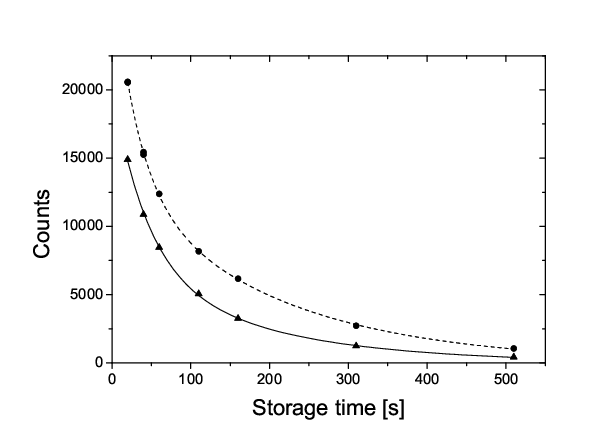
For the test of the PS ring we successfully employed UV-grade quartz windows coated by DPE (using spin-coating to obtain an optically flat surface), since DPS deteriorates under UV illumination, necessary for the co-magnetometer. The Fermi potential of DPE was also measured by means of cold neutron reflectometry, yielding neV.
The performance of the new chamber in terms of the neutron storage and depolarization, high-voltage stability, electrical resistivity and compatibility with the 199Hg magnetometer is similar or better than for a quartz chamber [11].
IV.3 Magnetometry
In order to investigate the possibility to improve the co-magnetometer sensitivity a detailed theoretical model, based on actual geometry of the system, has been developed, which aims at calculating the parameters, which affect the precision of the measurement. Based on the model, possible improvements have been identified and are being pursued [15].
In order to better control systematic effects, the magnetic field and its gradients will be monitored and stabilized using an array of laser optically pumped Cs-magnetometers [16]. For the external magnetometry, a system of Cs magnetometers around the UCN chambers (and ideally delivering vector information on the magnetic field, as in principle possible from newly developed double-resonance alignment magnetometers [17]) will be used for three tasks: i) stabilization of the magnetic field, ii) stabilization of the magnetic field gradient(s), iii) monitoring of the magnetic field. The first basic version of the system is already operational.
IV.4 Detection system
The higher UCN density which will be available at the PSI source calls for new fast detectors able to cope with higher rates. Recently the activities have progressed along two main directions: 1) the comparative study of UCN detector performances, with emphasis on their efficiency as well as on their background sensitivities; and 2) the test of geometries for the simultaneous analysis and detection of the two UCN spin components [12].
An extensive comparison between Cascade-U (GEM-type) detectors and 6Li doped glass scintillators (GS3, GS10, GS20) indicated higher efficiency of the scintillators for velocities in the range from 6 to 12 m/s.

The prototype polarization analysis system consists of two arms, each of them equipped with an adiabatic spin-flipper (SF), a spin analyzer (magnetized iron foil) and a detector (Fig. 3). The transmissions integrated over the whole UCN velocity distribution have been found to be around for both arms and are velocity independent in the range from 4 to 9 m/s. The asymmetry between both arms, obtained from the counting rates with the respective spin flipper ON and OFF, measured for the UCN velocities ranging from 4 to 7 m/s, is close to 80% (with the actual beam polarization around 90%). Further optimization of the system is planned.
V Phase II: Measurement at PSI
The concept for the Phase II setup is shown in Fig. 4. From left to right, the UCN pass through the superconducting polarizer magnet, a custom designed VAT UCN vacuum valve, a UCN switch valve with its connections up into the UCN trap, down into the detection system and horizontally through-going to a second VAT UCN valve. The maximum number of UCN is obtained by minimizing the vertical distance between the storage chamber and the input guide. Not shown here are the monitor detector system in the fill line, the vacuum system, the thermal housing and a possibly required compensation coil system.

A sensitivity increase by a factor of is anticipated due to the higher UCN intensity and better systematic control (based on the results of present R&D, see the previous section).
VI Phase III: Double Chamber Setup
The next generation setup will have a vertical field configuration and cylindrical, vertically stacked double UCN chambers inside a horizontal, cylindrical, multilayer -metal shield. Additional gain in sensitivity is expected due to a larger trap volume (), better adaptation to the UCN source (), longer running time () and electric field increase ().
Better control over systematics will be secured by the advantages of the double setup itself, possible velocity sensitive UCN detection and by the improved control over magnetic field, provided by the new shield, a field stabilization system and enhanced magnetometry, described below in more detail.

VI.1 Magnetometry
Magnetometry-wise we plan to combine co-magnetometry (improved magnetometry, R&D on and ), with field control by multiple Cs-sensors and two large volume magnetometers, also read by Cs magnetometers.
The magnetometry setup is displayed in Fig. 6, with vacuum chamber (1), Cs magnetometer array (2) for both, B-field measurement and read-out, 2 large magnetometer vessels (3), rectangular shaped UCN guides (4), valves (5) and double-chamber (6). The Cs magnetometer array will have multiple sensor heads (of order 64–128, not shown) and a co-magnetometry system (not shown) based on at least one out of three R&D options (, , ) will be used.
Initially, is provided by a reservoir (13). Spin-polarized is produced by the method of metastable optical pumping [18] in a cylindrical optical pumping cell (11) where a weak gas discharge is maintained to populate the metastable (3S1) states of . Following polarization, the gas at around 1 mbar is compressed into a buffer-cell (10) by means of a nonmagnetic piston compressor (9). This polarization and compression cycle is repeated until a pressure of about 100 mbar is reached in the buffer-cell. Then the gas is expanded via transfer-lines and suitable valves (7) into the magnetometer vessels. It should be noted that the whole pumping and compression unit is outside the multilayer -metal shield (8), in order not to disturb the electric and magnetic field conditions.

Our feasibility studies show that the proposed magnetometer is capable of tracing tiny magnetic field variations of fT during a typical UCN storage cycle of 200 s and can additionally monitor the gradients with high precision [23].
VII Summary
We propose improving the in-vacuum technique and performing a competitive experiment in steps, delivering first results in about 4 years (i.e., 2 years after set-up at the running PSI UCN source) with a five-fold improved sensitivity to a level of cm and reaching a sensitivity of cm in 6–8 years.
Several collaborations around the world aim at improved EDM experiments. The new cryogenic EDM searches [19, 20, 21, 22] aim at producing high UCN densities in super-fluid helium and performing also the EDM experiment directly in this medium.
In view of the experimental challenges of more precise EDM experiments, the competition of different groups using varying, complementary techniques could be crucial. While being on a similar time scale and with comparable sensitivity, our approach uses a different technique and offers unique features for systematic control, especially with respect to magnetometry.
References
- [1] S. Dar, The neutron EDM in the SM: A review, arXiv:hep-ph/0008248.
- [2] A. Sakharov, JETP Lett. 5 24 (1967).
- [3] C.A. Baker et al., Phys. Rev. Lett. 97 131801 (2006).
- [4] J.M. Pendlebury et al., Phys. Rev. A 70, 032102 (2004).
- [5] S.K. Lamoreaux, R. Golub, Phys. Rev. A 71, 032104 (2005).
- [6] A.L. Barabanov, R. Golub and S.K. Lamoreaux, arXiv:nucl-ex/0512014.
- [7] P.G. Harris and J.M. Pendlebury, Phys. Rev. A 73, 014101 (2006).
- [8] S. Abel et al., Nucl. Phys. B 606 151–182 (2001).
- [9] T. Falk et al., Nucl. Phys. B 560 3 (1999).
- [10] F. Atchison et al., Nucl. Instr. and Meth. A 552, 513 (2005).
- [11] M. Kuźniak, PhD thesis, Jagiellonian University, in preparation.
- [12] G. Rogel, PhD thesis, LPC, in preparation.
- [13] A. Knecht, PhD thesis, Universität Zürich, in preparation.
- [14] S.K. Lamoreaux, ILL report ILL88LA1T (1988).
- [15] S. Roccia, PhD thesis, LPSC, in preparation.
- [16] A. Weis and R. Wynands, Opt. Las. Engineer. 43, 387 (2005).
- [17] G. Di Domenico et al., Phys. Rev. A 76, 023407 (2007).
- [18] G. Eckert et al., Nucl. Instr. Meth. A 320, 53 (1992).
- [19] http://minoserv.maps.susx.ac.uk/nedm/
- [20] T.M. Ito, J. Phys.: Conf. Ser. 69, 012037 (2007).
- [21] http://p25ext.lanl.gov/edm/edm.html
- [22]
M. van der Grinten,
International Workshop on Particle Physics with Slow Neutrons, Grenoble, 2008.
http://www.ill.eu/news-events/
workshops-events/slow-neutron/program - [23]
W. Heil,
International Workshop on Particle Physics with Slow Neutrons, Grenoble, 2008.
http://www.ill.eu/news-events/
workshops-events/slow-neutron/program