Giant optical anisotropy in cylindrical self-assembled InAs/GaAs quantum rings
Abstract
Using a single-particle atomistic pseudopotential method followed by a many-particle configuration interaction method, we investigate the geometry, electronic structure and optical transitions of a self-assembled InAs/GaAs quantum ring (QR), changing its shape continously from a lens-shaped quantum dot (QD) to a nearly one dimensional ring. We find that the biaxial strain in the ring is strongly asymmetric in the plane perpendicular to the QR growth direction, leading to giant optical anisotropy.
pacs
73.21.La, 73.22.-f, 71.35.-yRecently, a novel nano-structure, quantum ring (QR), has been fabricated via the self-assemble techniques,[1] in various semiconductor systems, such as In(Ga)As/GaAs, [1, 2, 3, 4, 5] InAs/InP, [6, 7] InP/GaInP, [8] and Si/Ge[9] etc., with controlled sizes and shapes. Like the self-assembled quantum dots, the QRs have discrete energy levels due to the 3D confinement effects. However, a QR differs from a QD because of its non-simply connected topology, and therefore offers a unique opportunity to study the physical effects in addition to the confinement effects, such as the Aharonov-Bohm effect,[10, 11] and quantized magnetic susceptibility,[12] etc.
The electronic structure of self-assembled QRs have been explored via the electron charging experiment [13] and the photoluminescence (PL) spectra of charged excitons. [14, 15] On the other hand, most of the theoretical studies on the QRs are still at the continuum theory level, such as the effective mass approximations (EMA),[16, 12, 17, 18, 19, 20] method,[21] and the local spin density approximation,[22] etc., assuming 1-dimensional, [16] 2-dimensional, [12, 19, 20] and 3-dimensional model confinement potentials. [17, 21, 23] These studies provide valuable qualitative knowledge about the single-particle electronic structures, [21, 20, 24, 23] as well as the many body effects [22, 25, 19] of the QRs. However, it has been shown that an atomistic theory is necessary to capture the subtle features, such as energy level splittings,[26] shell filling [27] and exciton fine structures [28] etc. at single dot level. The atomistic effects are expected to be even more important for the QRs because the QRs have much larger surface area to volume ratio than the QDs of similar sizes.

In this paper, we investigate the electronic structures and optical transitions of realistic self-assembled InAs/GaAs QRs via an atomistic pseudopotential method.[29] We change the geometries of QRs from a lens-shaped QD to a narrow ring, by continously increasing the inner radius of the ring. We then study the strain profiles, the single-particle energy levels, as well as the optical transitions of the QRs with respect to the inner radius. The QRs have more complicate strain profiles than the QDs, due to their complicate topology. We show that the biaxial strain of QRs is strongly asymmetric in the plane perpendicular to the QR growth direction, leading to single-particle energy level crossing and giant optical anisotropy (even in cylindrical QRs).

Figure 1 depicts the cross sections of the QRs with their structural parameters, embedded in a 606060 GaAs matrix. The QRs are assumed growing along the [001] direction, on the top of a 1-monolayer wetting layer. The outer radius of the QR is measured from the center of the base to the outside edge of the ring, whereas the inner radius is defined to be the distance from center of the base to the inner circle. At , the QR is a lens-shaped quantum dot. [30] Therefore, by increasing the inner radius, we continously change the QR from a lens-shaped quantum dot to a one-dimensional quantum wire as . We fix the height of the quantum ring = 2.5 nm, outer radius =12.5 nm. and vary the inner radius from -12.5 nm (lens-shaped dot) to 6 nm. Alloy QRs and rings of larger outer radii give very similar results.
The single-particle energy levels and wavefunctions of the rings are obtained by solving the Schrödinger equations,
| (1) |
where the total electron-ion potential is a superposition of local, screened atomic pseudopotentials , [26] i.e. . The atom positions are obtained by minimizing the strain energies using the valence force field (VFF) method. [31, 32] Equation (1) is solved using the “Linear Combination of Bloch Bands” (LCBB) method. [29] The exciton energies and optical transitions are calculated via a configuration interaction (CI) method, [33] in which the exciton wavefunctions are expanded as the linear combination of Slater determinants constructed from the single-particle electron and hole wavefunctions.
Strain profiles: Figure 2 (a-d) depict the biaxial strain,
| (2) |
of the QR, for =-12.5 (lens-shaped dot), -3, 0 and 3 nm, respectively. For the lens-shaped dot, the biaxial strain is almost isotropic in the (001) plane. However, with the increasing of the inner radius , the biaxial strain becomes asymmetric in the (001) plane: the biaxial strain along the [110] direction becomes larger than that along the [10] direction. As the inner radius increases further, the difference of biaxial strain between the two directions becomes significant. One clearly see the biaxial strain peaks around the inner edge of the ring along the [110] direction at =0 nm and =3 nm in Fig. 2(c),(d). Since the hole confinement potential strongly depend on the biaxial strain, as a consequence, the strain-modified potentials for holes (not shown) are also asymmetric in the (001) plane.

Single-particle energy levels and wavefunctions: The electron and hole single-particle energy levels are shown in Fig. 3 (a),(b) respectively, as functions of . The orbital labels , , etc. are given by continuously monitoring the changing characters of the wavefunctions (see Fig. 4). We denote the , orbitals with peaks along the [10] direction , and those of peaks along the [110] direction , . For lens-shaped dot, the - and - energy spacings are nearly equal. For electrons, the two orbitals are nearly degenerate, as well as the two levels. However, for holes, the , levels show quite large (8 - 10 meV) energy splitting. [26, 34] The 2 state is close in energy to the states, suggesting that the confinement potential is close to a parabolic potential. [35] As we increase , we found that all the confined electron (hole) levels decrease (increase) first and then increase (decrease). We attribute the decreasing (increasing) of the energy levels at small to the strain effects after a close examination of the strained confinement potentials. The energy level turning points are indicated by the small arrows in Fig.3. The turning points of the and 2 levels, are about -2 to -3 nm, whereas the turning points of states are at larger inner radius =-1 nm. The turning points of the states are at about =1 nm for both electrons and holes, larger than those of and orbitals. After the turning point, the confined energy levels increase rapidly with the increasing of , especially for the and states. The 2 states become unconfined at 2 nm.
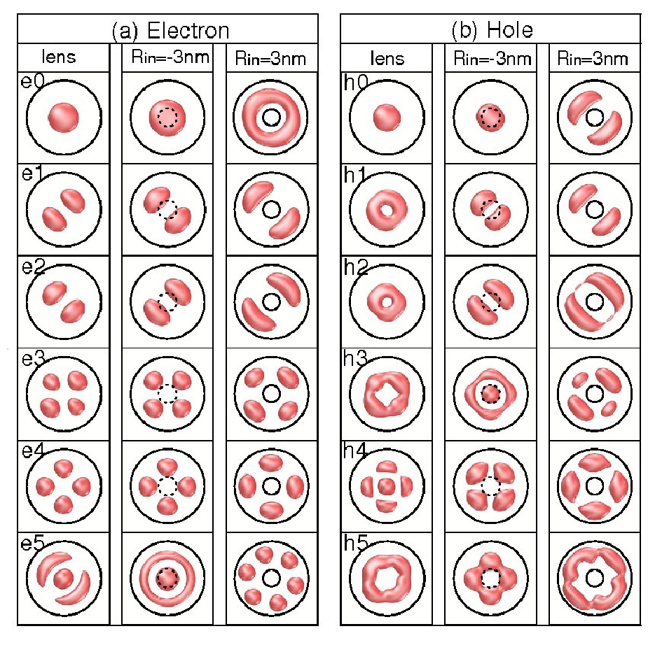
The trend of the electron energy levels as functions of the of the QRs can be understood by examining the wavefunctions of each level, shown in Fig. 4(a, b) for the six lowest confined electron and hole states. For lens-shaped QDs, the electron wavefunctions are the (), (, ), (, ) and 2 () orbitals respectively, in the order of increasing energy, whereas for holes, the 2 orbital is between the two levels. The character that distinguishes the 2 orbital from the orbitals is that the 2 orbital has a maximum at the center of the dot, whereas the orbitals have nodes at the dot center. The electron 2 orbital becomes unconfined after 0 nm, and is actually a state at 3 nm. The , 2 states, having maximum density at the dot center, are most sensitive to , as the states feel strong confinement potential from the inner circle of the ring with increasing of , leading to increasing of the level energy much faster than other states. Their wavefunctions also change dramatically from disk-like states at 0 nm (i.e., has the maximum at center of the ring), to ring-like (i.e., hollow at the center of the ring) at 0 nm. In contrast, the and orbitals have nodes at the ring center, and do not feel the confinement potential until at much larger . As a consequence, the electronic structures of the QRs deviate significantly from those of the QDs: (i) The - energy level spacing is much smaller than the - energy level spacing; (ii) The 2 level is no longer (nearly) degenerate with the two levels.
We observe several energy level crossings with respect to in Fig. 3, including the level crossing between electron 2 state and state at =0 nm, the hole 2 state with two states at = -3 and 0 nm, as well as the two electron (hole) orbital at = -3 (-4) nm. The level crossing of different angular momentum, (e.g. the 2 and states) is due to the confinement effect, as discussed above, whereas the level crossing between the two hole and states is due to the biaxial strain effects.

Optical transitions: We calculate the optical transitions spectrum in QRs, and the results are shown in Fig. 5 (a-d) for = -12.5, 0, 3, 6 nm, respectively. We show the polarized transition intensities in both [110] and [10] directions, as the transitions are almost linearly polarized in these two directions. The primary exciton energy is shifted to zero for each for clarity, and the transition peaks are marked by their leading transition characters. For example, the primary exciton transition is a (electron) to (hole) transition. We show also the - and - transitions. As we see, the energy differences between the -, - and - transitions decrease significantly with the increasing of inner radius, reflecting the change of single particle level spacings. The transition intensities also change dramatically with respect to . For example, the - and - transitions are much weaker in the QRs than in the dots. At = 6 nm, a significant to transition appears, because the envelope wavefunctions of electron state and hole states are no longer (nearly) orthogonal at this .
Interestingly, even though the total transition intensity of primitive exciton does not change much with respect to , the transition intensity polarized along the [10] becomes much stronger than that of the [110] direction. We calculate the optical polarization anisotropy , defined as the ratio of the transition intensities along the [110] and 0] direction, i.e., [26]
| (3) |
for the - transitions. For lens-shaped QDs [Fig. 5 (a)], is slightly smaller than (=1.09), agree with previous calculations.[26] However, with increasing of the inner radius, decrease dramatically. At = 6 nm, is only about 0.30, meaning the transition in the [10] direction is about 3 times stronger than in the [110] direction. Since the QRs studied here are cylindrical, the giant optical anisotropy is because of the “atomic symmetry factor” [26] due to the asymmetric biaxial strain.
To conclude, we have investigated via a single-particle atomistic pseudopotential and a many-particle CI methods, the electronic structures and optical transitions of self-assembled InAs/GaAs QRs. We find that even in cylindrical InAs/GaAs quantum rings, the biaxial strain is strongly asymmetric in the (001) plane, where the biaxial strain along the [110] direction is much larger than that along the [10] direction. The asymmetric strain induces single-particle energy level crossing, and lead to giant optical anisotropy. The optical anisotropy can be examined in future experiments and should be taken account of in designing QR devices.
L.H. acknowledges the support from the Chinese National Fundamental Research Program 2006CB921900, the Innovation funds and “Hundreds of Talents” program from Chinese Academy of Sciences, and National Natural Science Foundation of China (Grant No. 10674124).
References
- [1] J. M. Garcia, G. Medeiros-Ribeiro, K. Schmidt, T. Ngo, J. L. Feng, A. Lorke, J. Kotthaus, and P. M. Petroff, Appl. Phys. Lett. 71, 2014 (1997).
- [2] S. Huang, Z. Niu, Z. Fang, H. Ni, Z. Gong, and J. Xia, Appl. Phys. Lett. 89, 031921 (2006).
- [3] C.-Y. Huang, M.-C. Wu, S.-Y. Lin, J.-H. Dai, and S.-C. Lee, J. Cryst. Growth 301, 841 (2007).
- [4] D. Granados, J. M. Garcia, T. Ben, and S. I. Molina, Appl. Phys. Lett. 86, 071918 (2005).
- [5] Z. Gong, Z. C. Niu, S. S. Huang, Z. D. Fang, B. Q. Sun, and J. B. Xia, Appl. Phys. Lett. 87, 093116 (2005).
- [6] T. Raz, D. Ritter, and G. Bahir, Appl. Phys. Lett. 82, 1706 (2003).
- [7] J. Sormunen, J. Riikonen, M. Mattila, J. Tiilikainen, M. Sopanen, and H. Lipsanen, Nano Letter 5, 1541 (2005).
- [8] P. J.Wipakorn and R.Somchai, Microelectronic Engineering 84, 1548 (2007).
- [9] J. Cui, Q. He, X. M. Jiang, Y. L. Fan, X. J. Yang, F. Xue, , and Z. M. Jiang, Appl. Phys. Lett. 83, 2907 (2003).
- [10] Y. Aharonov and D. Bohm, Phys. Rev 115, 485 (1959).
- [11] U. F. Keyser, C. Fühner, S. Borck, R. J. Haug, M. Bichler, G. Abstreiter, and W. Wegscheider, Phys. Rev. Lett. 90, 196601 (2003).
- [12] T. Chakraborty and P. Pietilainen, Phys. Rev. B 50, 8460 (1994a).
- [13] A. Lorke, R. J. Luyken, A. O. Govorov, J. P. Kotthaus, J. M. Garcia, and P. M. Petroff, Phys. Rev. Lett. 84, 2223 (2000).
- [14] R. J. Warburton, C. Schaflein, D. Haft, F. Bickel, A. Lorke, K. Karrai, J. M. Garcia, W. Schoenfeld, and P. M. Petroff, Nature 405, 926 (2000).
- [15] D. Haft, C. Schulhauser, A. O. Govorov, R. J. Warburton, K. Karrai, J. M. Garcia, W. Shoenfeld, and P. M. Petroff, Physica E 13, 165 (2002).
- [16] H. F. Cheung, Y.Gefen, E. K. Riedel, and W. H. Shih, Phys. Rev. B 37, 6050 (1988).
- [17] S. Li and J. Xia, J. Appl. Phys 89, 3434 (2001).
- [18] S.-S. Li and J.-B. Xia, J. Appl. Phys. 91, 3227 (2002).
- [19] J. Song and S. E. Ulloa, Phys. Rev. B 63, 125302 (2001).
- [20] J. M. Llorens, C. Trallero-Giner, A. Garcia-Cristobal, and A.Cantarero, Phys. Rev. B 64, 035309 (2001).
- [21] J. Planelles, W. Jaskolski, and J. I. Aliaga, Phys. Rev. B 65, 033306 (2001).
- [22] J. I. Climente, J. Planelles, M. Barranco, F. Malet, and M. Pi, Phys. Rev. B 73, 235327 (2006).
- [23] I. Filikhin, V. M. Suslov, and B. Vlahovic, Phys. Rev. B 73, 205332 (2006).
- [24] T. Chakraborty and P. Pietilainen, Phys. Rev. B 50, 8460 (1994b).
- [25] F. Pederiva, A. Emperador, and E. Lipparini, Phys. Rev. B 66, 165314 (2002).
- [26] A. J. Williamson, L.-W. Wang, and A. Zunger, Phys. Rev. B 62, 12963 (2000).
- [27] L. He, G. Bester, and A. Zunger, Phys. Rev. Lett. 95, 246804 (2005).
- [28] G. Bester, S. Nair, and A. Zunger, Phys. Rev. B 67, 161306(R) (2003).
- [29] L.-W. Wang and A. Zunger, Phys. Rev. B 59, 15806 (1999).
- [30] Rigiously speaking, when , the QR is not a real ring. However, to simplify the discussion, we still call it a ring in this paper.
- [31] P. N. Keating, Phys. Rev. 145, 637 (1966).
- [32] J. L. Martins and A. Zunger, Phys. Rev. B 30, R6217 (1984).
- [33] A. Franceschetti, H. Fu, L.-W. Wang, and A. Zunger, Phys. Rev. B 60, 1819 (1999).
- [34] L. He and A. Zunger, Phys. Rev. B 73, 115324 (2006).
- [35] For a cylindrical QDs, the degeneracy of energy levels is at most two. However, for a dot with parabolic confinement, the 2 level also accidentally degenerate with the levels.