The ALICE HMPID detector ready for collisions at the LHC
Abstract
ALICE has been specifically optimized to study heavy-ion collisions at the LHC, up to a charged particle density of 8000 per unit of rapidity in central heavy-ion collisions at = 5.5 TeV. The High Momentum Particle Identification Detector (HMPID) has a proximity focusing geometry with a liquid Cherenkov radiator coupled to Multi-Wire Pad Chambers (MWPC) equipped with CsI photocathodes, over a total active area of 11 . It has been designed to identify charged pions and kaons in the range 1 3 GeV/ and protons in the range 2 5 GeV/. The as-built detector and all relevant subsystems (gas, liquid , cooling and control) are described. Installation issues and first commissioning results are also presented.
Keywords:
HMPID , ALICE , RICH , CsI photocathodePACS
25.6 , 34.8.a , 29.40.Ka1 Introduction
The ALICE experiment at CERN is optimized to study heavy-ion collisions at center-of-mass energy 5.5 GeV at the LHC [1, 2]. The High Momentum Particle Identification Detector [2, 3] (HMPID) in ALICE is dedicated to the inclusive measurement of charged particles, both in heavy-ion and proton-proton collisions. The single arm design of the HMPID covers 5% of the central barrel region of ALICE at mid-rapidity. The HMPID enhances the particle identification capabilities of ALICE, extending the momentum range further than is accessible to individual central tracking detectors: ITS, TPC and TOF. The HMPID can identify charged pions and kaons in the momentum range and protons up to 5 GeV/ with 3 separation.
This paper focuses on the as-built description of the HMPID and the first commissioning results. Further details of HMPID hardware and physics goals can be found in [2, 3, 4].

2 Description of the installed HMPID
2.1 The HMPID layout
The High Momentum Particle Identification Detector consists of seven identical proximity focusing type Ring Imaging Cherenkov Counter (RICH) modules. The modules are located on an independent support cradle and mounted at the two o’clock position of the ALICE space frame as shown in Fig. 1. The seven modules (1.5 m 1.5 m each) cover 0.6 in pseudo-rapidity and 57.6o in azimuth. The chambers are tilted and positioned in a cupola-like structure to focus on the nominal interaction point, at 4.7 m distance from the modules. The layout of the chambers on the support cradle maximizes the HMPID acceptance for two-particle correlation studies at high-.
2.2 Radiators and the liquid circulation system
Fast charged particles, emerging from the collisions, create Cherenkov photons traversing the low chromacity liquid radiators (with index of refraction of at nm). The choice of the radiator liquid determines the momentum threshold; for liquid the momentum threshold is given by 1.21 , where is the particle mass.
Each HMPID module is equipped with three radiator vessels made of NEOCERAM®, providing 15 mm radiator thickness. The NEOCERAM (a glass-ceramic material) is thermally compatible to the fused silica plates, used as UV-transparent windows.
The radiator vessels are filled and emptied at a constant flow by the liquid circulation system. To ensure safe remote operation the system is built on the gravity flow principle. To minimize the contamination of water and oxygen (less than 5 ppm), and to achieve the best transparency of the liquid radiator for Cherenkov photons, filters are implemented for purification. The liquid circulation system is scheduled to be completed and installed in its final location at the beginning of 2008.
2.3 The photo-detector
The Cherenkov photons created in the liquid radiator refract out from the fused silica windows and enter the proximity gap. The proximity volume is filled with pure at ambient pressure and temperature.
The Cherenkov photons are detected on the pad cathodes of Multi-Wire Pad Chambers (MWPC). Each module consists of 6 caesium iodide (CsI) covered photocathodes, 60 cm 40 cm each. Quantum efficiency 25% (at nm) is achieved with the 300 nm thick CsI covered photocathodes. The pad cathodes are segmented into 8 mm 8.4 mm pads to provide position sensitive information. Detailed description of the HMPID CsI photocathode production can be found in [5].
The total gas gain achievable is 5 104, with the cathodes kept at ground and a positive voltage of 2050 V applied to the anode wires.

2.4 Front End Electronics
The front-end electronics is located at the back side of the HMPID modules. The closure box is flushed with nitrogen and closed by a cooling panel, that removes the dissipated heat of the electronics, 450 W per module.
The front-end electronics is based on two dedicated ASIC chips, GASSIPLEX and DILOGIC [6], processing the analogue signals from the pad cathodes. The GASSIPLEX and the DILOGIC chips were successfully developed within the framework of the HMPID project in the ALCATEL-MIETEC 0.7 m technology.
The GASSIPLEX chip is a 16-channel analogue multiplexed low-noise signal processor. Preceding the HMPID commissioning, the noise of the front-end chips and the map of dead or noisy pads have been surveyed. The noise is found to be 1000 e RMS with a dispersion of less than 50 e, and the number of dead/noisy pads is found to be 200 out of 161280 pads.
The DILOGIC chip is a sparse data scan readout processor used for zero suppression and pedestal subtraction. Individual threshold and pedestal values can be processed for up to 64 channels. Data from the 7 HMPID modules are readout via 14 standard ALICE optical links (DDL) [7].
Digitization is performed using a commercial 12-bit ADC. The digitization and zero-suppression time does not depend on the occupancy, only on the multiplexing rate of 3 chips (48 channels), which makes the event overlap negligible even in the highest luminosity proton-proton collisions. Since particle identification is not possible in the HMPID without momentum information, only events with TPC information are of interest. The readout time after L2 trigger arrival (for the estimated 12% module occupancy) will be of the order of 300 s, hence the HMPID can perfectly cope with the readout rates foreseen for the TPC [8].
In total, 10080 GASSIPLEX and 3360 DILOGIC chips have been installed in the seven HMPID modules.
3 Installation and commissioning
All HMPID modules have been successfully installed on the supporting cradle and moved into the ALICE magnet on 26 September 2006, as shown in Fig. 2. Preceding the installation, five HMPID modules were tested in test beam and two modules in cosmic ray data taking [9].

While the HMPID is not operational, the modules are flushed with argon. After the installation of the HMPID modules on the support cradle in the experimental cavern and prior to moving the assembly into the ALICE magnet, a leak was detected in one of the radiator trays (in module 6). The loss of a single radiator (1 out of 21) represents 5% loss of acceptance. Due to the small impact on the physics potential of the detector and the not negligible risks, including delays, involved in the repair, it has been decided to install the detector inside the ALICE solenoid with 20 operational radiators while flushing the leaking one with methane.
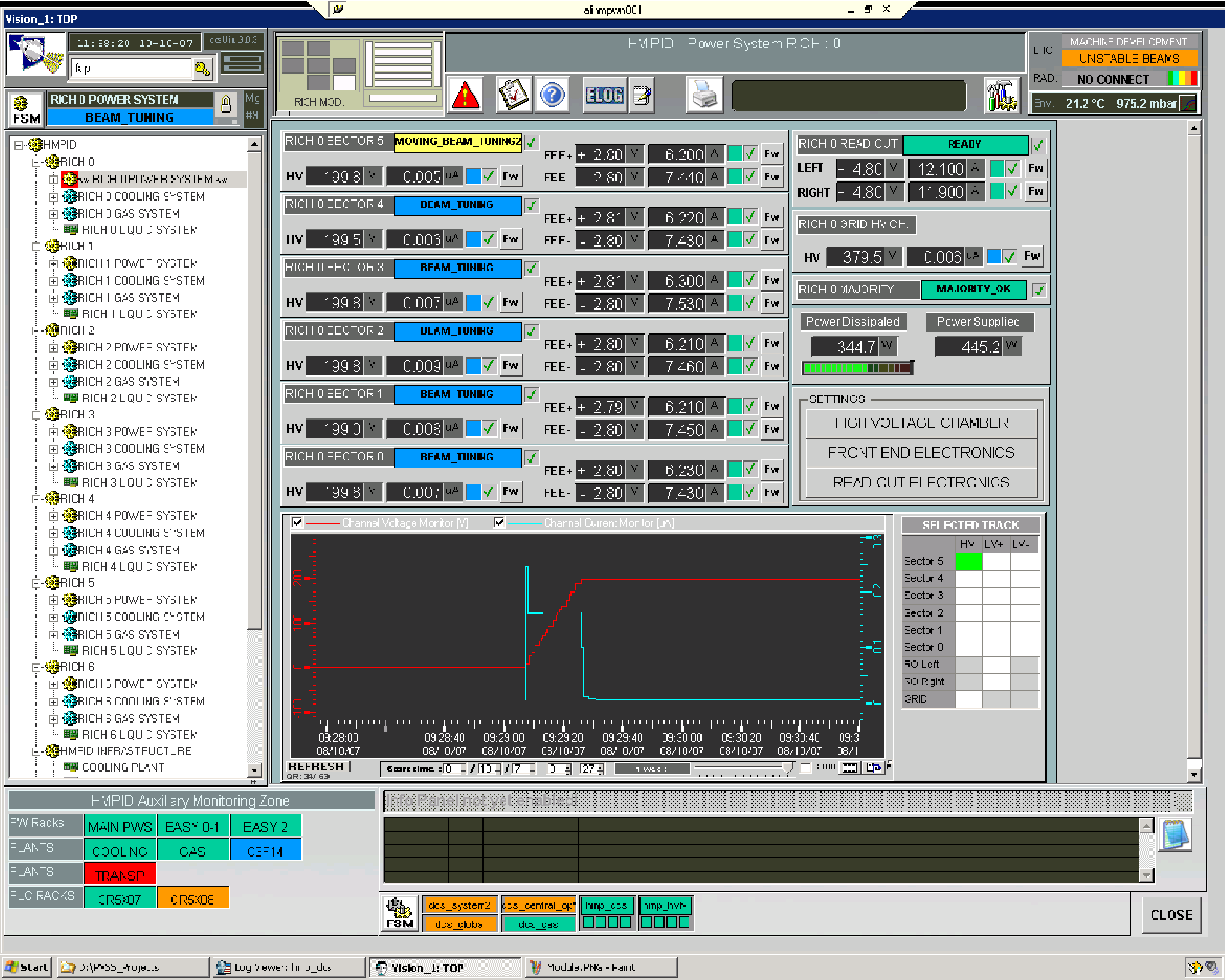
The safe operation of the detector under commissioning and in normal operation is achieved via the Detector Control System (DCS), developed within the HMPID project. Since July 2007 all HMPID modules are fully powered and controlled by DCS. Figure 3 shows the detector-oriented view of the fully powered HMPID, with most subsystems operational. The HMPID DCS controls the subsystems of gas, cooling, liquid circulation and transparency, high-voltage, low-voltage and the front end electronics as shown in Fig. 3. During the commissioning phase the alarm and interlock levels have been set for the full scale cosmic test of ALICE. For expert operation, the DCS provides access down to a single hardware element of the HMPID, in the device oriented view. Figure 4 shows the device oriented view of the high voltage modules during the high voltage ramp up of HMPID module 0.


A long term stability test of the fully powered HMPID has been performed under DCS control, archiving all relevant detector information in the central ALICE database. The continuous monitoring revealed a loose high voltage channel (in module 5). The standard high voltage (2050 V) cannot be applied on this channel; a lower high voltage setting is used. This may only allow the detection of charged particles, and not Cherenkov photons, in that high voltage sector. This represents a 2.4% (1 out of 42 high voltage channels) acceptance loss.
After the long term stability test, the systematic survey of the read-out electronics for noisy and dead channels has been repeated. The first results of the HMPID module 0 and photocathode 0 are shown in Figs. 5 and 6. Figure 5 shows the mean pedestal value for each photocathode pad. The average pedestal value is found to be 110 out of 4092 ADC channels. Figure 6 shows the width of the pedestal distribution for each photocathode pad. The average width is 1.1, equivalent to a charge 1000 e RMS, with small number of outlying pads. This agrees with the expected value of the noise from the read-out electronics as reported in [6].
4 Summary
The as-built High Momentum Particle Identification Detector has been presented, along with its commissioning and installation details. A leak has been found in one of the 21 radiators and one loose high voltage channel out of 42 high voltage channels has been discovered. However, the physics goals of HMPID are not significantly compromised by the small acceptance loss. All seven HMPID modules were mounted on the support cradle and installed in the ALICE magnet in September 2006. Full control of the HMPID modules has been achieved via the Detector Control System in July 2007. The liquid circulation system is scheduled to be completed at the beginning of 2008. Hence, the HMPID will be ready for the data taking by the expected start of the LHC in the summer of 2008.
References
- [1] ALICE Collaboration, Technical proposal, CERN/LHCC/95-712.
- [2] F. Carminati et al. (ALICE Collaboration), J. Phys. G 30, 1517 (2004).
- [3] ALICE Collaboration, ALICE HMPID Technical Design Report, CERN/LHCC 98/19.
- [4] B. Alessandro et al. (ALICE Collaboration), J. Phys. G 32, 1295 (2006).
- [5] A. Di Mauro et al., ALICE Internal Note 2007-003.
- [6] J. C. Santiard, K. Marent, CERN-ALICE-PUB-2001-49; J. C. Santiard, Nucl. Instrum. Meth. A 518, 498 (2004); H. Witters, J. C. Santiard, P. Martinengo, Dilogic-2: CERN-ALICE-PUB-2000-010.
- [7] W. Carena et al., ALICE Internal Note 2001-47.
- [8] ALICE Collaboration, Technical Design Report of the Trigger, Data Acquisition, High Level Trigger and Control System, CERN/LHCC/2003-062.
- [9] A. Gallas (ALICE Collaboration), Nucl. Instrum. Meth. A 553, 345 (2005).