Superposition-Coded Concurrent Decode-and-Forward Relaying
Abstract
In this paper, a superposition-coded concurrent decode-and-forward (DF) relaying protocol is presented. A specific scenario, where the inter-relay channel is sufficiently strong, is considered. Assuming perfect source-relay transmissions, the proposed scheme further improves the diversity performance of previously proposed repetition-coded concurrent DF relaying, in which the advantage of the inter-relay interference is not fully extracted.
I Introduction
The exploitation of cooperation among users has been studied in recent years as a means for improving diversity performance for single-antenna wireless systems. Due to the half-duplex limitation, standard cooperative diversity protocols (e.g. [1] [2]) usually require two time-division-multiple-access (TDMA) time slots to finish each signal codeword’s transmission. Although diversity gain can be improved over conventional TDMA direct source-destination transmission, standard cooperation protocols result in lost spectral efficiency, especially in the high signal-to-noise ratio (SNR) region.
To overcome the multiplexing limitation of standard protocols, an advanced successive relaying protocol (independently proposed by [3], [4], and [5] in different contexts) has been considered such that two relays take turns helping the source to mimic a full-duplex relay. The single-source single-antenna network studied in [5] has been extended to a two-source multiple-antenna (at the destination only) scenario in [6] and [7], in which the scheme is termed concurrent decode-and-forward (DF) relaying. For such a protocol, a two-source two-relay one-destination cooperation network has been considered. The two sources’ standard DF relaying steps are combined so that the degrees of the freedom of the channel are efficiently used and the multiplexing loss induced by standard protocols can be effectively recovered.
The major issue with concurrent DF relaying is that the interference generated among the two relays significantly affects the system diversity-multiplexing tradeoff (DMT) performance. In [7], two specific scenarios (i.e. the isolated-relay and strong-interference scenarios) are examined to investigate the impact of the inter-relay interference. However, for both scenarios, reference [7] requires the relays to use repetition coding to retransmit their source messages. In this paper, we argue that such an assumption is not very efficient for the strong-interference scenario because the advantage of the inter-relay interference, which is also useful information, is not fully extracted. Specifically, for the strong-interference scenario, instead of requiring each relay to forward its own source’s codeword, we permit it to use superposition coding to transmit both sources’ codewords. In this way, the achievable diversity gain can be further improved with the sacrifice of only one extra transmission time slot. When the signal frame length is large, the multiplexing loss induced by this extra transmission time is negligible.
The rest of this paper is organized as follows. In Section II, we briefly review the DMT behavior of the repetition-coded concurrent DF relaying protocol and present the superposition-coded concurrent DF relaying protocol for a two-source network. The system model is generalized to an -source network in Section III. Finally, we offer simulation results and discussions in Section IV.
II Two-Source Concurrent DF Relaying
We first study a five-node network with two single-antenna sources and , two single-antenna half-duplex DF relays and , and one -antenna destination . The transmitted messages from each source are divided into different frames, each containing codewords denoted as , , . Two independent Gaussian random codebooks are used by the two sources and are known by both relays. Each codeword is independently chosen from the associated Gaussian random codebook and has unit average power. A slow, flat, block Rayleigh fading environment is assumed, where the channel remains static for one coherence interval (two frame periods) and changes independently in different coherence intervals. Moreover, we assume a uniform power allocation scheme, i.e. the total transmit power in each transmission time slot remains the same and each terminal transmits with equal power.
II-A Repetition-Coded Concurrent DF Relaying
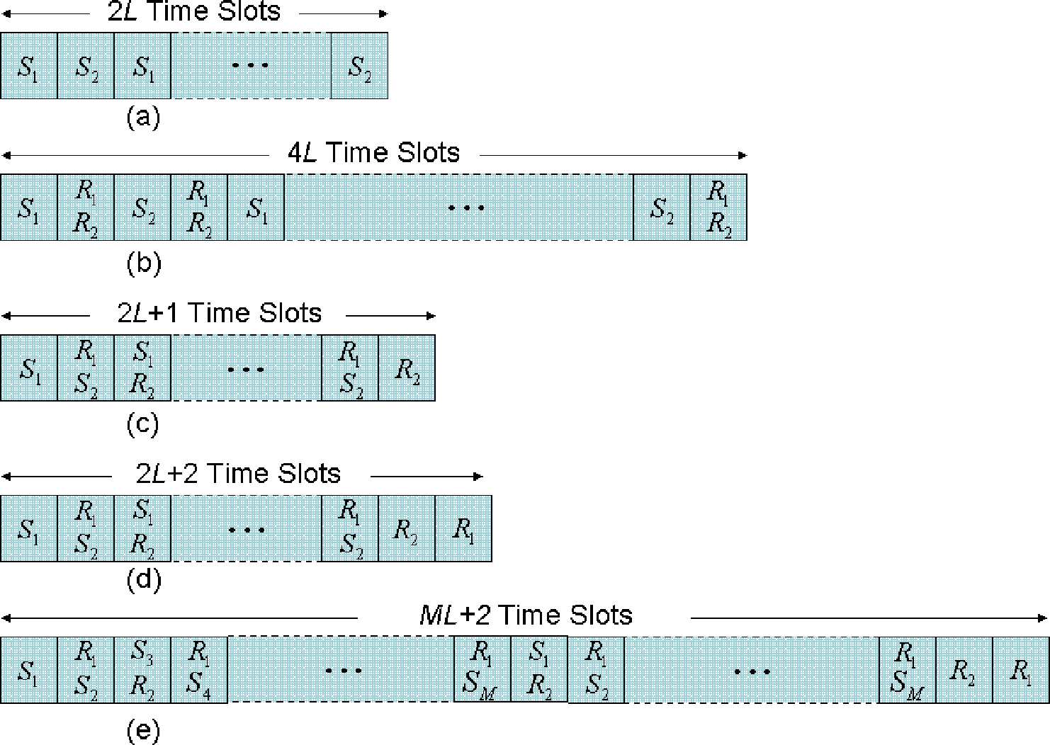
For such a two-relay scenario, due to the half-duplex operation of the relays, for each source codeword, the space-time-coded standard DF relaying protocol [8], which is a practical example of the protocol proposed by [2], requires each source to broadcast the codeword to both relays and the destination in the first time slot (broadcasting step). The relays then retransmit the codeword (using a distributed Alamouti space-time block code) to the destination in the second time slot (relaying step), as shown in Fig. 1 (b). Assuming the source messages are correctly decoded by the relays, the standard protocol can provide significant diversity gain improvement over TDMA direct source-destination transmission. However, to finish the transmission of the codewords from the two sources to the destination, time slots must be used. Compared with TDMA direct transmission displayed in Fig. 1 (a), which needs only time slots, the standard protocol loses spectral efficiency, especially for the high SNR region.
In order to compensate for the multiplexing gain reduction induced by the standard protocol, for concurrent DF relaying [6] it is assumed that each source is individually assisted by one relay (i.e. and are supported by and respectively) and one source’s broadcasting step is combined with the other source’s relaying step. As displayed in Fig. 1 (c), except in the first and the last time slots, one relay and one source always communicate with the destination simultaneously so that only time slots are needed to finish the transmission of the codewords.
It is clear that the interference generated among relays can significantly degrade the system capacity and diversity performance. However, the two relays may be isolated [4], which means the quality of the inter-relay link is much worse than those of the source-relay links. In this case, the inter-relay interference is trivial compared with source-relay transmissions and thus can be ignored. Since the relays are assumed to simply repeat their source codewords after decoding them, we refer to this transmission scheme as the repetition-coded concurrent DF relaying throughout the paper.
Define the diversity gain and multiplexing gain as those in [9] and assume the system is symmetric [10], where the two sources have identical multiplexing gains . Assuming the source-relay links are sufficiently strong such that the relays can always perfectly decode their source messages, the DMT achieved by each source for the repetition-coded concurrent DF relaying protocol can be expressed by [7]
| (1) |
The repetition-coded concurrent DF relaying significantly improves the diversity performance over TDMA direct transmission (with DMT ) except for a multiplexing loss . Such multiplexing loss decreases as increases and can be neglected for large frame length . However, compared with the space-time-coded standard DF relaying (with DMT ), the repetition-coded concurrent DF relaying obtains smaller diversity gain when since each codeword is only forwarded by one relay.
II-B Superposition-Coded Concurrent DF relaying
A strong-interference scenario [11], where the channel between the two relays is sufficiently stronger than the source-relay links, is also studied in [7]. In this case, each relay is required to decode the interference signal first and subtract it from the received signal before decoding the desired signal. The good quality of the inter-relay channel guarantees that each relay can correctly decode the interference before decoding its desired source codeword with very high probability. Therefore, the interference between relays does not limit the system DMT performance. However, for such a strong-interference scenario, reference [7] still assumes that each relay only forwards its own source message (the desired signal). In fact, since the interference signal is the transmitted codeword from the other source, in this paper, we argue that we can make use of the interference signal to further improve the system diversity gain. Specifically, we permit the relays to use superposition coding [11] to retransmit both sources’ messages, i.e. instead of retransmitting its desired source codeword, each relay transmits the sum of the interference codeword and the desired codeword. To guarantee every codeword to be transmitted via three independent paths, time slots are used to finish the transmission of the codewords from the two sources. The transmission of the two frames can be described as follows:
Time slot 1: broadcasts to both and ; and remain silent.
Time slot 2: forwards to and transmits . listens to while being interfered by from . receives from and from .
Time slot 3: forwards to . transmits . listens to while being interfered by from . receives from and from .
Time slot 4: forwards to . transmits . listens to while being interfered by from . receives from and from .
This process repeats until the th time slot.
Time slot : retransmits to and .
Time slot : decodes, re-encodes and retransmits to .
Unlike the repetition-coded case, from the rd to the th time slot, the interference signal received by each relay is not only the other relay’s desired source codeword, but also the codeword transmitted by the relay itself during the previous time slot. Because each relay has full knowledge of its own transmitted codeword, it can subtract its previously transmitted codeword from the received signal before decoding without any difficulty. After all the codewords are received, performs joint decoding to recover the source information. We refer to this protocol as the superposition-coded concurrent DF relaying and its time-division channel allocation and the transmission schedule (from the rd time slot to the th time slot) are illustrated in Fig. 1 (d) and Fig. 2 respectively.

Assuming perfect source-relay transmissions, the proposed protocol mimics a -user multiple access single-input multiple-output (SIMO) channel (except that the dimensions of the signals are expanded in the time domain):
| (2) |
in which the equivalent channel matrix is
| (3) |
where is the channel fading vector between node and the destination, 0 denotes an all zero vector, , is the receive signal vector at the th time slot, is the transmit signal vector, n is a unit power complex circular additive white Gaussian noise (AWGN) vector at the destination, and means the average received SNR. It is worth noting that the scaling factors and come from the uniform power allocation assumption and have no consequence for the system infinite-SNR DMT performance. In terms of the achievable DMT, we have the following theorem.
Theorem 1
In a symmetric scenario, on assuming that the source codewords are correctly decoded by the relays, the achievable DMT for each source of the superposition-coded concurrent DF relaying protocol (i.e. the system model in (2)) is given by
| (4) |
Proof:
For a symmetric -user multiple-access SIMO system described in (2), following the capacity calculation in [12], there are source transmission rate constraints for a given realization of the channel:
| (5) |
| (6) |
and
| (7) |
where denotes the th column of H. The system diversity gain is thus the smallest diversity gain calculated by all the constraints from (5) to (7).
Consider an multiple-input multiple-output (MIMO) channel (each codeword has multiplexing gain so that the average transmission rate )
| (8) |
where , , and when is odd and , , and when is even. For infinite SNR, the task of finding the smallest diversity gain obtained by each constraint from (5) to (7) is the same as finding the smallest diversity gain achieved by the system (8) for every [6].
When , the system model in (8) is a SIMO system. The achievable DMT is clearly . When , applying a method similar to that used for the DMT calculation for the ISI channels in [13], it is not difficult to show that . Because the overall system diversity gain is dominated by the smallest one for all , it thus is (i.e. the case where ) the same as the right hand side of (4). Due to limited space, here we omit the detailed proof, which can be found in [14]. ∎
Theorem 1 indicates that superposition-coded concurrent DF relaying obtains the maximal diversity gain and maximal multiplexing gain . This means that the diversity performance of the repetition-coded concurrent DF relaying is further improved by making use of the inter-relay interference. Therefore, unlike the repetition-coded case, where the achievable diversity gain is larger than that of the space-time-coded standard protocol only in the high region, superposition-coded concurrent DF relaying strictly outperforms the standard protocol within the range of all possible multiplexing gains (except for the worst case , where the two protocols have identical performance). Although there exists a slight difference for the maximal achievable multiplexing gain between the repetition-coded and superposition-coded concurrent DF relaying protocols (due to the extra transmission time slot), when is large this difference is negligible and the maximal multiplexing gains for both protocols approach . The multiplexing loss induced by the standard protocol is fully compensated in both protocols. Fig. 3 displays an example (, ) of the DMT comparison.

Throughout this paper, we assume that the source-relay transmissions are perfect so that the system diversity gain is not limited by the quality of source-relay links. Making use of the inter-relay interference can thus further improve the diversity performance over the simple repetition-coded protocol. One may argue that, in practical systems, such good source-relay links may not be able to be guaranteed and the system DMT performance may be affected by any weak source-relay link. In fact, in a general cooperation network, there usually exist multiple terminals which can act as potential relays. If the number of potential relays is very large, the probability of selecting at least one relay pair such that one relay can correctly decode one source and the other relay can correctly decode the other source is sufficiently high. In this case, the system DMT performance behaves the same as the case in which the transmissions between the sources and their relays are always successful. Therefore, our assumption is actually not uncommon in reality. The impact of using relay selection schemes in multiple-relay scenarios on the system DMT performance is currently under investigation.
III -Source Concurrent DF Relaying
The two-source system model can also be extended to a large network with single-antenna sources, two single-antenna relays and one -antenna destination, as has been done for the repetition-coded case in [7]. The basic idea is that the sources communicate with the common destination using TDMA and the two relays take turns helping each source until the transmission of the codewords from each source is finished. Therefore, time slots are used to complete the transmission of the codewords from the sources. Assuming perfect decoding at the relays, the time-division channel allocation is illustrated in Fig. 1 (e) (where is even) and in terms of the achievable DMT, we have the following corollary to Theorem 1.
Corollary 1
In a symmetric scenario, on assuming perfect source-relay transmissions, the achievable DMT for each source of the superposition-coded -source concurrent DF relaying protocol is given by
| (9) |
Corollary 1 implies that, compared with repetition-coded concurrent DF relaying for the -source network, which needs time slots and obtains DMT , the superposition-coded protocol improves the maximal achievable diversity gain from to , but reduces the maximal achievable multiplexing gain from to . However, if is large, the maximal multiplexing gain difference is negligible and both gains approach (the maximal multiplexing gain for TDMA direct transmission) so that the multiplexing loss is fully recovered and the requirement of being large is relaxed. Clearly, when , the system model is the single-source scenario studied in the content of the successive relaying protocol proposed in [5]. This means that superposition coding can also be used in successive relaying to further increase diversity performance and thus (9) offers a generalized result.
IV Simulation Results and Discussions
In this section, we compare our two-source superposition-coded concurrent DF relaying scheme with other schemes discussed in Section II in terms of error probability through Monte-Carlo simulations. The source messages are assumed to be always correctly decoded by the relays. In our simulations, we consider the signal frame lengths and for the repetition-coded and superposition-coded concurrent DF relaying protocols, respectively. For this choice, both schemes obtain the maximal multiplexing gain . These two cases are actually the worst cases for both schemes. (Recall that when , the superposition-coded concurrent DF relaying has the same DMT performance as the space-time-coded standard protocol and we therefore do not consider this case.) And following the analysis in Section II, when (), the performance of the repetition-coded (superposition-coded) concurrent DF relaying would be even better than those shown in the following simulations.
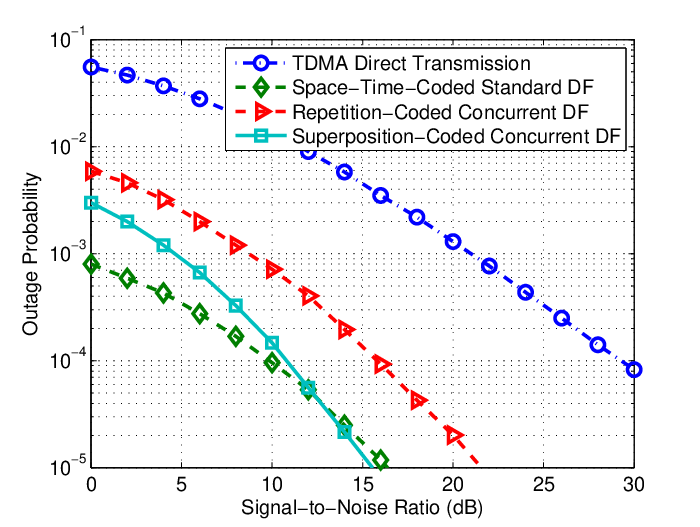
Fig. 4 displays the outage probabilities comparison for different schemes when multiplexing gain (i.e. the transmission rates are not fixed and scale with SNR). Following the analysis in Section II, it can be seen that the DMT curves for the standard protocol and the repetition-coded concurrent DF relaying intersect, which means the two protocols have the same diversity gains. Clearly, this diversity gain is further improved by the use of the superposition coding in the relays. Such a diversity performance can be seen by comparing the slopes of the high-SNR outage probability curves for different schemes.
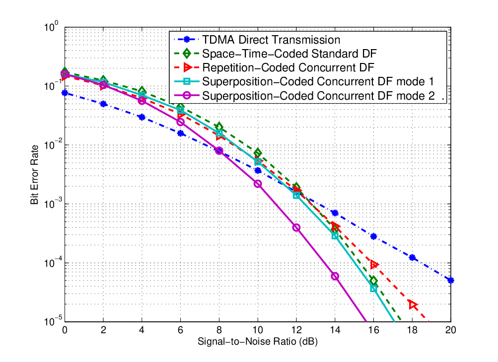
We also study the error performance for uncoded symbols for different schemes. For a fair comparison, we consider -QAM, -QAM and -QAM modulation for TDMA direct transmission, concurrent DF relaying and the standard protocol respectively so that all schemes have identical average transmission rates at two bits per channel use (BPCU). For decoding at the destination, a maximal ratio combining (MRC) receiver is used for TDMA direct transmission and the standard protocol, and a maximum likelihood sequence detector (MLSD) receiver is used for the concurrent DF relaying protocols. Moreover, we consider two different ways to use superposition coding in the relays. The first one (denoted as mode 1 in Fig. 5) is similar to superposition modulation [15] and we require each relay to retransmit the direct sum of its desired signal and the interference. The second one is similar to code superposition [16] (denoted as mode 2). In this case, each codeword transmitted by the relays represents the XORed version of the two signals.
From Fig. 5, it can be seen TDMA direct transmission has the worst high-SNR performance. Although repetition-coded concurrent DF relaying improves the error performance due to the signal protection by the relays, it performs worse than space-time-coded standard DF relaying since each codeword is only forwarded by one relay. Clearly, superposition-coded concurrent DF relaying has the same diversity order as the standard protocol. Furthermore, mode 2 superposition coding outperforms mode 1 by nearly dB, which confirms the advantage of code superposition analyzed in [16]. This observation suggests interesting future work in applying network coding techniques in our approach.
Acknowledgment
C. Wang’s, I. Krikidis’ and J. S. Thompson’s work reported in this paper has formed part of the Delivery Efficiency Core Research Programme of the Virtual Centre of Excellence in Mobile & Personal Communications, Mobile VCE, www.mobilevce.com. This research has been funded by EPSRC and by the Industrial Companies who are Members of Mobile VCE. Fully detailed technical reports on this research are available to Industrial Members of Mobile VCE. Y. Fan’s and H. V. Poor’s work was supported in part by the U.S. National Science Foundation under Grants ANI-03-38807 and CNS-06-25637. The authors acknowledge the support of the Scottish Funding Council for the Joint Research Institute with the Heriot-Watt University which is a part of the Edinburgh Research Partnership.
References
- [1] J. N. Laneman, D. N. C. Tse, and G. W. Wornell, “Cooperative diversity in wireless networks: Efficient protocols and outage behavior,” IEEE Trans. Inform. Theory, vol. 50, no. 12, pp. 3062–3080, Dec. 2004.
- [2] J. N. Laneman and G. W. Wornell, “Distributed space-time-coded protocols for exploiting cooperative diversity in wireless networks,” IEEE Trans. Inform. Theory, vol. 49, no. 10, pp. 2415–2425, Oct. 2003.
- [3] B. Rankov and A. Wittneben, “Spectral efficient protocols for half-duplex fading relay channels,” IEEE J. Select. Areas Commun., vol. 25, no. 2, pp. 379–389, Feb. 2007.
- [4] S. Yang and J.-C. Belfiore, “Towards the optimal amplify-and-forward cooperative diversity scheme,” IEEE Trans. Inform. Theory, vol. 53, no. 9, pp. 3114–3126, Sept. 2007.
- [5] Y. Fan, C. Wang, J. S. Thompson, and H. V. Poor, “Recovering multiplexing loss through successive relaying using simple repetition coding,” IEEE Trans. Wireless Commun., vol. 6, no. 12, pp. 4484–4493, Dec. 2007.
- [6] C. Wang, Y. Fan, and J. S. Thompson, “Recovering multiplexing loss through concurrent decode-and-forward (DF) relaying,” Wireless Per. Commun., to appear.
- [7] C. Wang, Y. Fan, J. S. Thompson, and H. V. Poor, “On the diversity-multiplexing tradeoff of concurrent decode-and-forward relaying,” in Proc. IEEE Wireless Communications & Networking Conference (WCNC) 2008, Las Vegas, NV, 31 Mar. - 3 Apr. 2008.
- [8] P. A. Anghel, G. Leus, and M. Kaveh, “Distributed space-time cooperative systems with regenerative relays,” IEEE Trans. Wireless Commun., vol. 5, no. 11, pp. 3130–3141, Nov. 2006.
- [9] L. Zheng and D. N. C. Tse, “Diversity and multiplexing: A fundamental tradeoff in multiple-antenna channels,” IEEE Trans. Inform. Theory, vol. 49, no. 5, pp. 1073–1096, May 2003.
- [10] D. N. C. Tse, P. Viswanath, and L. Zheng, “Diversity-multiplexing tradeoff in multiple access channels,” IEEE Trans. Inform. Theory, vol. 50, no. 9, pp. 1859–1874, Sept. 2004.
- [11] T. M. Cover and J. A. Thomas, Elements of Information Theory. New York: Wiley, 1991.
- [12] B. Suard, G. Xu, H. Liu, and T. Kailath, “Uplink channel capacity of space-division-multiple-access schemes,” IEEE Trans. Inform. Theory, vol. 44, no. 4, pp. 1468–1476, July 1998.
- [13] L. Grokop, “Diversity multiplexing tradeoff in ISI channels,” Master’s thesis, Department of Electrical Engineering and Computer Science, University of California at Berkeley, May 2005.
- [14] C. Wang, Y. Fan, J. S. Thompson, and H. V. Poor, “The diversity-multiplexing tradeoff for concurrent decode-and-forward relaying cooperative diversity,” in preparation.
- [15] E. G. Larsson and B. R. Vojcic, “Cooperative transmit diversity based on superposition modulation,” IEEE Commun. Lett., vol. 9, no. 9, pp. 778–780, Sept. 2005.
- [16] L. Xiao, T. E. Fuja, J. Kliewer, and J. Daniel J. Costello, “Cooperative diversity based on code superposition,” in Proc. IEEE International Symposium on Information Theory (ISIT) 2006, Seattle, WA, July 2006.