Coherent Graphene Devices: Movable Mirrors, Buffers and Memories
Abstract
We theoretically report that, at a sharp electrostatic step potential in graphene, massless Dirac fermions can obtain Goos-Hänchen-like shifts under total internal reflection. Based on these results, we study the coherent propagation of the quasiparticles along a sharp graphene p-n-p waveguide and derive novel dispersion relations for the guided modes. Consequently, coherent graphene devices (e.g. movable mirrors, buffers and memories) induced only by the electric field effect can be proposed.
pacs
81.05.Uw, 73.63.-b, 73.21.-b, 42.25.-pA totally reflected light beam can laterally shifted from the position expected by a geometrical trajectory, an effect termed the “Goos-Hänchen” (GH) shift [1]. This effect can be qualitatively attributed to evanescent wave penetration into the medium with a smaller refractive index. Some theories, such as stationary phase models [2], current-flux models [3], etc., have been developed to formulate this effect. Recently, the exploration of negative refraction brought on new interest in this subject since it can lead to negative GH shifts [4, 5]. Based on negative GH shifts and waveguide theory [6], the “trapped rainbow” storage of light in a tapered left-handed heterostructure (LHH) offers a novel mechanism to bring light to a complete standstill efficiently and coherently, which may lead to applications in optical data processing, storage and quantum optical memories [7].
Graphene, a monolayer of carbon atoms, has attracted great interest since it was successfully prepared [8, 9, 10]. The interaction between electrons and the two-dimensional (2D) honeycomb lattice of carbon atoms results in a gapless band structure near Dirac cones with a linear (photon-like) electron-hole dispersion, which gives rise to new quasiparticles. Besides, the hopping of electrons between the two triangular sublattices introduces pseudospin 1/2 and chirality to the quasiparticles, which can be analogous to massless neutrinos [9, 10]. Therefore, the quasiparticles can possess the low-energy dynamics effectively described by a Dirac equation with Fermi velocity m/s, and they are also called massless Dirac fermions. Furthermore, long phase coherence length [11] and tunable Fermi levels based on electric field effects [8, 12] have been experimentally observed in graphene. Based on the above properties, recent theoretical research has focused on the coherent transport properties of quasiparticles in the electrically gated graphene structures, including Klein tunneling [13, 14], focusing of electron flow [15], confined states and resonant tunneling in quantum wells [16, 17], coherent transmission through graphene strips [18, 19], etc. All these studies imply that it might be hard to fully and coherently control the group velocity of the massless quasiparticles in the graphene structures induced by electric field effects alone. In some cases, graphene quantum dots [20, 21, 22] or magnetic fields [23] can be introduced, but for trapping only.

In this paper, however, we have discovered the possibility to coherently decelerate, trap and re-accelerate the massless Dirac fermions along a sharp graphene p-n-p waveguide by using a tunable electric field. The waveguide in our scheme can be produced in a bulk graphene sheet by electrostatic gates only, which avoids the complex effects of the graphene strip edges [18, 19, 20, 21] and the magnetic fields [23]. Our results are the electronic counterpart to the trapped rainbow effect in optics [7]. Before discussing the coherent propagation of quasiparticles along a sharp graphene p-n-p waveguide, we first examine the total internal reflection (TIR) of quasiparticles at a sharp electrostatic step potential and focus on the GH-like shift, which is inspired by the similarities between the reflection and refraction of photons and those of graphene quasiparticles at interfaces [15, 10].
In our scheme, we theoretically consider the coherent ballistic transport of quasiparticles and ignore the disorder as was also done in Refs. [13, 14, 15, 16, 17, 18, 19, 20, 21, 22, 23]. Moreover, since the electron-electron interaction can not severely distort the shapes of constant energy contours of low energy Fermi levels [24], it can be ignored as well [13, 14, 15, 16, 17, 18, 19]. We also assume that, the edge smearing length of the sharp potential is much smaller than the incident quasiparticle wavelength, but much larger than the lattice constant of graphene, which can prevent intervalley scatterings [14]. The quasiparticle dynamics is therefore governed by the 2D Dirac equation
| (1) |
where m/s is the Fermi velocity, are the Pauli matrices, is the momentum operator, the potential is -independent with the Heaviside step function H, and is the eigenenergy. Because a unit cell of the graphene honeycomb lattice contains two sublattices A and B, the state is expressed by the two-component spinor , where and represent the smooth enveloping functions at each sublattice. The conservation of leads to . Thus, Eq. (1) gives
| (2a) | |||
| (2b) | |||
The wave functions in the two different regions can be written in terms of incident, reflected and evanescent waves with the incident angle . Figure 1 shows a p-n junction for clarification. We define , , and . In region , we have
| (3) | |||
where , , () is the incident (reflected) wave function and is the reflection amplitude. In region , the evanescent wave is
| (4) |
where the decay constant , , and is the transmission amplitude. Because and are nonzero real numbers, we can obtain the inequalities
| (5) |
which is a necessary condition to obtain evanescent waves. When condition (5) is satisfied, the wavevector in region is smaller than in region , which is analogous to the propagation of light from a medium having a larger refractive index into one having a smaller refractive index. Hence, the critical angle for the TIR can be defined by . One can calculate the reflection amplitude with the boundary conditions of the wave functions at ,
| (6a) | |||||
| (6b) | |||||
where . From Eq. (6), we can get
| (7) |
where and .

Some further discussions follow. First, we compare the TIR of the massless Dirac fermions in graphene and that of the Dirac electrons in high energy physics [25, 26] because both of them are (pseudo)spin fermions. For the TIR of the Dirac electrons, the incident and reflected momentum states are well defined due to the conservation of momentum, but the spin has two states (e.g. parallel and anti-parallel to the momentum direction), which means there are two eigenstates for incidence and reflection, respectively. Different eigenstates have different phase shifts, which can cause the splitting. However, for the TIR of the massless (neutrino-like) quasiparticles in graphene, the incident and reflected momentum states are well defined, and as a consequence, the pseudospin states are well defined due to the chirality. This means there is only one eigenstate for incidence and reflection, respectively. Similar to Dirac electrons, one can calculate and find the rotation of the pseudospin of the quasiparticles can not produce any extra phase shifts and the reflection amplitude provides the net phase shift for the reflected wave. Our analysis indicates that not only does the chirality of the massless quasiparticles ensure the absence of back-scattering for normal incidence [13, 14], but also no splitting under TIR, such as in Ref. [16]. Second, we also note the research on the nonlinear screening in the graphene p-n junction [27], which can lower the junction resistance. Nevertheless, in our scheme [e.g., Fig. 1(a)], the shift originates from the evanescent wave penetration into the p side having a smaller effective refractive index. The nonlinear screening near the interface can not severely affect the existence of the evanescent wave on the p side. In principle, this effect can thus be ignored in our theory.
Based on the above discussions and the stationary phase treatment [4, 25, 26], the lateral displacement is
| (8) | |||||
Note that Eq. (8) is not valid at the critical angle and . The results depicted in Fig. 2 can be directly analogous to the positive and negative GH shifts in optics [1, 4, 5]. Equations (7) and (8) also tell us that the phase and position of the reflected wave can be coherently controlled by adiabatically changing the gate voltages, which can make the step potential work as a “movable mirror”.


The negative GH-like shift of massless Dirac fermions at the sharp p-n junction suggests that, in analogy to the trapped rainbow effect of light in the LHH [7], the quasiparticles can have novel propagation properties in a p-n-p waveguide. For simplicity, we discuss here a symmetric p-n-p waveguide [Figs. 3(a) and 3(b)]. Therefore, Eq. (2) is still applicable, but the solutions and boundary conditions are different. In region , we have
| (9) |
In region , we have
| (10) |
In region , we have
| (11) |
where is the width of region . The boundary conditions result in
| (12a) | |||||
| (12b) | |||||
| (12c) | |||||
| (12d) | |||||
A transcendental equation can be derived from the coefficient determinant of Eq. (12), which is
| (13) |
The preceding relationships between , , , and give the dispersion relations between and for the guided modes. Condition (5) leads to , , for the p-n-p waveguide. Numerical calculations of the dispersion relations clearly indicate the slow positive (forward), zero and even negative (backward) group velocities of the quasiparticles depending on the gate voltages [Fig. 4(a)] and the widths [Fig. 4(b)].
More interestingly, the field-effect-dependent dispersion relations shown in Fig. 4(a) indicate the possibility to dynamically and coherently decelerate, stop and re-accelerate the guided quasiparticles. The detailed process is as follows. First, it is known that, when the quasiparticles are guided in the waveguide, the incident angle should be preserved due to the parallel interfaces [Fig. 3(a)]. Thus, assuming the quasiparticles are initially prepared in a forward propagating state shown at point A in Fig. 4(a), then one can adiabatically changing the gate voltages to transfer the forward propagating state to a trapped state at point B due to the preservation of the incident angle. After a certain storage time, the trapped state can be transferred to either the original state or a backward propagating state shown at point C. Consequently, it can be seen that the p-n-p waveguide is not only a waveguide, but also a “buffer” or “memory” for the quasiparticles in a coherent way.
To explain this process, we adopt the current-flux method [3] instead of the stationary phase treatment mentioned above. The current density in the different regions can be expressed by
| (14) |
with for the corresponding regions [16]. For the guided modes, we are only interested in their propagation along the p-n-p waveguide [the direction in Fig. 3(a)]. Hence, the flux , which also gives the group velocity of the quasiparticles, is given by
| (15) |
where for the guided components gives the positive current density in region , and for the evanescent components give the negative current densities in regions and . By adiabatically changing the gate voltages, we can coherently redistribute the current densities in the different regions. Consequently, the dynamics of the whole wave function are strongly influenced, and the group velocity can be coherently controlled. Our calculations show that Eq. (15) gives the same values of group velocities at the points A, B and C in Fig. 4(a). The current densities in the p-n-p waveguide are schematically illustrated in Fig. 5.
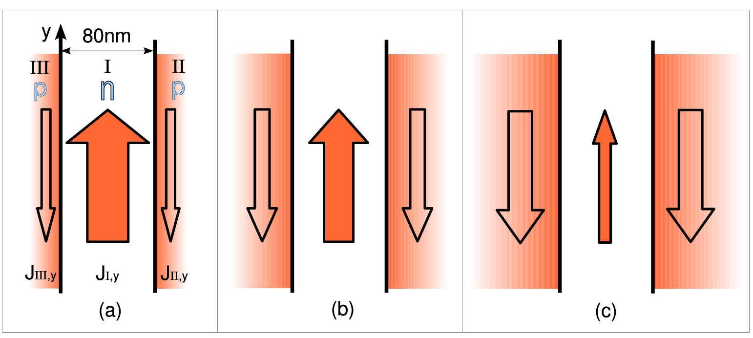
Additionally, the width-dependent dispersion relations shown in Fig. 4(b) also indicate the possibility to coherently decelerate and stop the guided quasiparticles by adiabatically reducing the width from point D to F while keeping the gate voltages unchanged, which is similar to the principle of Ref. [7]. After the storage, one can adiabatically change the gate voltages for retrieval.
In summary, we have demonstrated the GH-like shifts of massless Dirac fermions at an electrostatic step potential in graphene and the novel dispersion relations for the guided quasiparticle modes in a sharp graphene p-n-p waveguide. Our analysis shows that, based on the tunable electric field effects, the electrostatic step potential can function as a movable mirror for the incident quasiparticles, and the p-n-p waveguide can coherently buffer, store and retrieve the guided quasiparticles. These results may have interesting applications in the graphene-based quantum information processing.
We would like to acknowledge funding from NSF. L. Z. thanks A. Kovner, J. Javanainen, R. Zhou, T. Wang and F. Peng for fruitful discussions and helpful suggestions.
References
- [1] F. Goos and H. Hänchen, Ann. Phys. (Leipzig) 1, 333 (1947); ibid. 5, 251 (1949).
- [2] K. Artmann, Ann. Phys. (Leipzig) 2, 87 (1948).
- [3] R. H. Renard, J. Opt. Soc. Am. 54, 1190 (1964).
- [4] P. R. Berman, Phys. Rev. E 66, 067603 (2002).
- [5] I. Shadrivov et al., Appl. Phys. Lett. 83, 2713 (2003).
- [6] A. W. Snyder and J. D. Love, Optical Waveguide Theory (Chapman and Hall, New York, 1983).
- [7] K. L. Tsakmakidis, A. D. Boardman, and O. Hess, Nature (London) 450, 397 (2007).
- [8] K. S. Novoselov et al., Science 306, 666 (2004).
- [9] A. H. Castro Neto et al., arXiv:0709.1163v2.
- [10] C. W. J. Beenakker, Rev. Mod. Phys. 80, 1337 (2008).
- [11] F. Miao et al., Science 317, 1530 (2007).
- [12] K. S. Novoselov et al., Nature (London) 438, 197 (2005); Y. Zhang et al., Nature (London) 438, 201 (2005); H. B. Heersche et al., Nature (London) 446, 56 (2007); M. C. Lemme et al., IEEE Electron Device Lett. 28(4), 282 (2007); B. Huard et al., Phys. Rev. Lett. 98, 236803 (2007); J. R. Williams et al., Science 317, 638 (2007).
- [13] V. V. Cheianov and V. I. Fal’ko, Phys. Rev. B 74, 041403(R) (2006).
- [14] M. I. Katsnelson et al., Nature Phys. 2, 620 (2006).
- [15] V. V. Cheianov et al., Science 315, 1252 (2007).
- [16] J. Milton Pereira, Jr. et al., Phys. Rev. B 74, 045424 (2006).
- [17] J. Milton Pereira, Jr. et al., Appl. Phys. Lett. 90, 132122 (2007).
- [18] J. Tworzydło, et al., Phys. Rev. Lett. 96, 246802 (2006).
- [19] M. I. Katsnelson, Eur. Phys. J. B. 51, 157 (2006).
- [20] P. G. Silvestrov and K. B. Efetov, Phys. Rev. Lett. 98, 016802 (2007).
- [21] B. Trauzettel, et al., Nature Phys. 3, 192 (2007).
- [22] A. Matulis et al., Phys. Rev. B 77, 115423 (2008).
- [23] A. De Martino et al., Phys. Rev. Lett. 98, 066802 (2007).
- [24] R. Roldán et al., Phys. Rev. B 77, 115401 (2008).
- [25] D. M. Fradkin and R. J. Kashuba, Phys. Rev. D 9, 2775 (1974); ibid. 10, 1137 (1974).
- [26] S. C. Miller, Jr. et al., Phys. Rev. Lett. 29, 740 (1972).
- [27] L. M. Zhang, et al., Phys. Rev. Lett. 100, 116804 (2008).