Nanomechanical Spin-Polarizer
Abstract
Torsional oscillations of a free-standing semiconductor beam are shown to cause spin-dependent oscillating potentials that spin-polarize an applied charge current in the presence of intentional or disorder scattering potentials. We propose several realizations of mechanical spin generators and manipulators based on this piezo-spintronic effect.
pacs
71.70.Ej,71.70.Fk,72.25.-b,85.85.+jThe field of spintronics comprises the search for novel logic and sensing devices that employ the electron spin degree of freedom by (excess) spin generation and manipulation (Žutić et al. 2004). In the conventional approach spins are injected into normal conductors by ferromagnetic metals using an applied electrical bias. An alternative method is the spin-pumping by a moving magnetization (Brataas et al. 2002; Tserkovnyak et al. 2005). A net-spin generation is possible without involving ferromagnets at all by making use of the spin-orbit interaction, e.g. by a time-dependent gate acting on a two-dimensional electron gas (Governale et al. 2003; Tang et al. 2005), or the spin Hall effect (Murakami et al. 2003).
Spin-transfer by spin-flip scattering in metal structures causes mechanical torques (Fulde and Kettemann 1998; Mohanty et al. 2004; Kovalev et al. 2007). Mal’shukov et. al. (Mal’shukov et al. 2005) predict that a spin-polarized current can induce torsional vibrations in a semiconductor beam by strain-induced spin-orbit interaction. The same authors speculate about a possible reverse effect, viz. that mechanical motion could induce a spin-polarized current.
In this Letter, we propose a nano-electro-mechanical system (NEMS) that generates spins by the coupling to torsional oscillations of a free-standing semiconductor bridge/beam/rod that is actuated, e.g., by magnetomotive (Mohanty et al. 2004; Huang et al. 2005), electrostatic (Fennimore et al. 2003) or piezoelectric (Masmanidis et al. 2007) forces. Subject to an oscillating strain, the spin-orbit interaction in the semiconductor generates a spin splitting which, in the presence of a bias, leads to a spin current. In analogy with piezo-electricity, in which elastic strain induces free charges, this can be termed a piezo-spintronic effect. We illustrate the physical principle by a conducting wire in the electric quantum limit in which only a single quantized subband is occupied. Subsequently, we generalize the results to the multi-channel case. We also demonstrate by numerical simulations that the effect survives the disorder that can be expected in real systems and discuss the conditions under which it can be observed.
Let us consider a beam with length and rectangular cross section of width and thickness () (see Fig 1) that connects two semi-infinite conducting reservoirs. Results can be easily generalized to axially symmetric rods such as catalytically grown nanowires (Duan et al. 2001). The conducting material is a semiconductor that is grown on top of a dielectric. Without loss of generality we assume here a structure consisting of a conducting medium on top of an insulator both being thick.
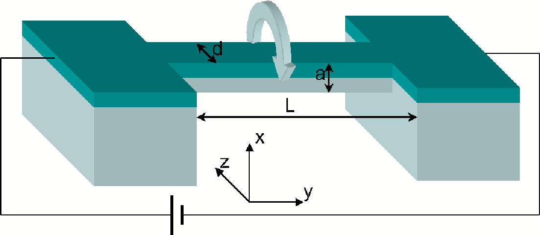
The leading modification of the conduction band Hamiltonian of a semiconductor due to lattice strain reads (Pikus and Titkov 1984):
| (1) |
where is the effective mass, are elements of the strain tensor, and are Pauli matrices. By focusing on narrow-gap semiconductors, we may disregard the terms proportional to the small parameter (Pikus and Titkov 1984).
We are interested in the lowest energy vibrations of the beam that can be described by an isotropic elastic continuum model (Landau and Lifshitz 1986). Elastic flexural (bending) modes cause only diagonal strains that couple to the electrons only via the small term (see Eq. (1)) (Mal’shukov et al. 2005). The strain due to torsional (twisting) vibrations is given by (Landau and Lifshitz 1986):
| (2) |
where is the derivative of the torsion angle with respect to . The function characterizes the cross-section geometry of the beam and depends here only on and . It satisfies the equation with vanishing boundary conditions (Landau and Lifshitz 1986). We adopt the thin plate geometry which leads to and the Hamiltonian:
| (3) |
Eq. (3) is similar to a Rashba spin-orbit Hamiltonian; however, electrons can move here in three dimensions and the coupling strength is time and position dependent.
We now turn to the lowest electronic subband limit, disregarding intrinsic spin-orbit interaction, e.g. Rashba type, and assuming that the strain induced perturbation is weak. The free-electron lowest energy states read where is the lowest subband and is a spinor function. The projected one-dimensional Hamiltonian then reads:
| (4) |
where is the potential due to impurities and we disregarded terms . Electrons with up and down spins turn out to be uncoupled and subject to effective vector potentials of opposite sign, . Since , this vector potential does not describe an effective magnetic but a spin-dependent electric field:
| (5) |
The equation of motion for the torsional angle of the beam reads
| (6) |
where is the moment of inertia of the cross-section about its center of mass, the mass density and is an elastic constant defined by the shape and material of the cantilever. for a plate with , and is the Lamé constant. The general solution of Eq. (6) is a plane wave , where is the wave number, , and is the sound velocity. Throughout this paper, we consider a doubly-clamped beam in which the lowest harmonic is excited, where and is the wave number (see Fig. 1). The standing mechanical wave creates an oscillating electric field that is exactly out of phase for spin-up and spin-down electrons. In the Born-Oppenheimer approximation, the strain induces a parametric potential (cf. Eq. (5)) that is adiabatically followed by the electrons.

The strain-induced potentials vary only slowly and do not yet spin-polarize a charge current significantly. However, defect scattering strongly amplifies the piezo-spintronic effect, as illustrated now by a single short-range potential scatterer located in the middle of the beam. Disregarding the small intrinsic effect caused by the probability that an electron with Fermi wave number is transmitted by the scatterer reads:
| (7) |
where . According to the Landauer conductance formula, the spin polarization of a charge current becomes:
| (8) |
where the Fermi energy . The spin-polarization oscillates in time with the beam vibration frequency.
Generalization to a multichannel wire is facilitated by the following gauge transformation
| (9) |
with , which leads to the transformed Hamiltonian:
| (10) |
| (11) |
It is convenient to choose . We allow many occupied subbands along the axis but restrict considerations to the lowest subband along the axis, which is the case for a laterally weakly confined two-dimensional electron gas. After projecting Eq. (10) to the lowest mode in the direction, we obtain the following two-dimensional Hamiltonian:
| (12) |
where , . can be interpreted as a spin precession length and describes two-dimensional disorder scattering. is here still arbitrary, but we limit our attention to the lowest vibrational mode as before.
The terms proportional to in Eq. (12) induce subband transitions; however, these do not affect transport when the precession length is larger than the width of the channel. In the limit of a long and narrow beam, we may again treat the time dependence of the Hamiltonian Eq. (12) parametrically in terms of the frequency . In the limit , we can further simplify Eq. (12) by disregarding subband transitions. A simple short-range wall potential does not lead to subband transitions either. Our system then reduces to a collection of independent channels, which lead to a total spin-current polarization
| (13) |
where is the index and the total number of transport channels. Here,
| (14) |
where is the wave number of an electron in the channel at the Fermi energy. In Fig. (2), we present results of Eq. (13) for the maximum mechanically induced spin-current polarization as a function of the beam width. The dashed line in Fig. (3) are the results of Eq. (13) for the spin-polarization as a function of time.

The idealized model above allowed us to illustrate the physics of piezo-spintronics. We now consider a more realistic model, including many electron modes, subband mixing and arbitrary forms of the potential . We numerically calculate the scattering matrix using the recursive Green’s function technique and the tight-binding representation of the Hamiltonian (12):
where is the on-site energy that includes and , ) is the hopping energy and is the hopping energy due to the spin-orbit interaction, in terms of the tight-binding lattice spacing . The bold lines in Fig. 3 display our numerical results for the polarization as a function of time for the short-range wall potential used above. We find good agreement with the analytical results for large aspect ratios of the beam, as expected. Deviation from the analytical results become noticeable when .

Finally, we model the potential by on-site Anderson disorder with energies distributed over a band width . The beam is represented as a discrete lattice and an ensemble averaging over impurity configurations is carried out. A single realization (without averaging) behaves similar to our single defect result in Fig. 3. Averaged results are presented in Fig. 4. The Anderson disorder strength can be measured by an effective 2D mean free path (Ando 1991) as . Here we consider ; and . When the Anderson disorder is weak, the spin polarization is almost a harmonic function of time. We may conclude that the piezo-spintronic effect is very robust, persisting in a disordered system, confirming the qualitative behavior of the analytical model with one dominating defect scatterer.
The choice of parameters above is motivated by the following estimates made for a silicon cantilever of size . The resonant frequency is , using the density of silicon and the Lamé constant . The maximum angle of torsion can be estimated by equating the energy dissipation during a cycle , where is the mechanical quality factor, with the energy input rate where is the actuating torque applied at the center of the beam. Electrostatic torques of have been already realized (Fennimore et al. 2003). Taking , and , we find . The corresponding spin-orbit precession length is and the spin splitting is using the bulk strain-spin-orbit coupling parameter for GaAs (Pikus and Titkov 1984) which is not expected to be affected strongly by the finite structure confinement (Winkler 2003). This leads to polarizations of the order of . In the presence of an applied DC voltage, the mechanical motion generates AC spin current. Alternatively, one can apply AC voltage synchronized with the mechanical motion to obtain a DC spin current. The thus created spin accumulation can be detected by e.g. a ferromagnetic side contact (Lou et al. 2006) or by the optical Kerr rotation (Kato et al. 2004).
In order to increase the polarization, one can use semiconductors with lower doping (smaller Fermi energy). The width of the rod can be tuned to capture the resonant features in Fig. 2. Rods with higher quality factors can have larger amplitude of oscillations leading to higher polarizations.
Summarizing, we propose a piezo-spintronic effect that is based on strain-induced coupling of the electron spin degree of freedom and mechanical vibrations in free standing semiconductor nanobeams. We show that time-dependent strain due to torsional mechanical oscillations can lead to a measurable spin polarization of an applied charge current. Mechanically generated spin-dependent potentials (mechanically-induced Zeeman splittings) can be also used for the manipulation of an applied spin currents. We propose ways to measure and increase such mechanically generated polarization that can be used for effective spin injection in spintronic based devices.
We thank Artem Abanov and Karel Výborný for helpful discussions. This work was supported by ONR under Grant No. 000140610122, by NSF under Grant no. DMR-0547875, and by SWAN-NRI.
References
- Žutić et al. (2004) I. Žutić, J. Fabian, and S. Das Sarma, Rev. Mod. Phys. 76, 323 (2004).
- Brataas et al. (2002) A. Brataas et al., Phys. Rev. B 66, 060404 (2002).
- Tserkovnyak et al. (2005) Y. Tserkovnyak et al., Rev. Mod. Phys. 77, 1375 (2005).
- Governale et al. (2003) M. Governale, F. Taddei, and R. Fazio, Phys. Rev. B 68, 155324 (2003).
- Tang et al. (2005) C. S. Tang, A. G. Mal’Shukov, and K. A. Chao, Phys. Rev. B 71, 195314 (2005).
- Murakami et al. (2003) S. Murakami, N. Nagaosa, and S.-C. Zhang, Science 301, 1348 (2003); J. Sinova et al., Phys. Rev. Lett. 92, 126603 (2004); Y. Tserkovnyak et al., Phys. Rev. B 76, 085319 (2007); I. Adagideli and G. E. Bauer, Phys. Rev. Lett. 95, 256602 (2005); T. Kimura et al., Phys. Rev. Lett. 98, 156601 (2007).
- Mohanty et al. (2004) P. Mohanty et al., Phys. Rev. B 70, 195301 (2004).
- Fulde and Kettemann (1998) P. Fulde and S. Kettemann, Ann. Phys. 7, 214 (1998).
- Kovalev et al. (2007) A. A. Kovalev, G. E. W. Bauer, and A. Brataas, Phys. Rev. B 75, 014430 (2007).
- Mal’shukov et al. (2005) A. G. Mal’shukov et al., Phys. Rev. Lett. 95, 107203 (2005).
- Huang et al. (2005) X. M. H. Huang et al., New J. Phys. 7, 247 (2005).
- Fennimore et al. (2003) A. M. Fennimore et al., Nature 424, 408 (2003).
- Masmanidis et al. (2007) S. C. Masmanidis et al., Science 317, 780 (2007).
- Duan et al. (2001) X. F. Duan et al., Nature 409, 66 (2001).
- Pikus and Titkov (1984) G. E. Pikus and A. N. Titkov, in Optical Orientation (North-Holland, Amsterdam, 1984).
- Winkler (2003) R. Winkler, Spin-orbit coupling effects in two-dimensional electron and hole systems (Springer, Berlin, (2003).
- Landau and Lifshitz (1986) L. Landau and E. Lifshitz, Theory of Elasticity, vol. 7 (Pergamon, New York, 1986), 3rd ed.
- Ando (1991) T. Ando, Phys. Rev. B 44, 8017 (1991).
- Lou et al. (2006) X. Lou et al., Phys. Rev. Lett. 96, 176603 (2006).
- Kato et al. (2004) Y. K. Kato, R. C. Myers, A. C. Gossard, and D. D. Awschalom, Science 306, 1910 (2004).