Development of a thermal ionizer as ion catcher
Abstract
An effective ion catcher is an important part of a radioactive beam facility that is based on in-flight production. The catcher stops fast radioactive products and emits them as singly charged slow ions. Current ion catchers are based on stopping in He and H2 gas. However, with increasing intensity of the secondary beam the amount of ion-electron pairs created eventually prevents the electromagnetic extraction of the radioactive ions from the gas cell. In contrast, such limitations are not present in thermal ionizers used with the ISOL production technique. Therefore, at least for alkaline and alkaline earth elements, a thermal ionizer should then be preferred. An important use of the TRIP facility will be for precision measurements using atom traps. Atom trapping is particularly possible for alkaline and alkaline earth isotopes. The facility can produce up to 109 s-1 of various Na isotopes with the in-flight method. Therefore, we have built and tested a thermal ionizer. An overview of the operation, design, construction, and commissioning of the thermal ionizer for TRIP will be presented along with first results for 20Na and 21Na.
Keywords:
Radioactive ion beam , Slowing of ions , Ion source , Ion catcher , Diffusion , Ionization , Hot cavityPACS
29.25.Ni , 29.90.+r , 34.35.+a , 41.75.Ak , 41.85.Ar, , , , , , , , , , , , , ,
1 Introduction
In the TRIP facility [1] radioactive nuclides are produced in a gas target using inverse reaction kinematics [2] and separated from the beam in a magnetic separator [3]. Typical energies range up to several 10 MeV per nucleon. The secondary beams from the magnetic separator have large transverse emittances and wide energy distributions. Thermalization is required in order to efficiently collect the produced isotopes and transport them further as a beam of ions.
A gas stopper [4] suitable for slowing of a large range of isotopes was initially considered as an ion catcher for the TRIP facility, but reduction of the extraction efficiency at high intensities [5], neutralization limits [6], and the required gas purity [7] led to the decision to use an alternative slowing method. This method employs a thermal ionizer (TI) ion catcher, the operation of which is based on hot cavity ion sources [8] such as used in ISOL (Isotope Separation On-Line) facilities. A TI allows high efficiencies to be reached for short-lived alkali and alkali earth isotopes which are of primary interest for the goals of TRIP [9, 10, 11, 12]. Moreover, the efficiency of the TI is independent of the secondary beam intensity.
In contrast to ISOL systems where the primary beam is fully stopped in the target-ion source system, at the TRIP facility only secondary isotopes (with several orders of magnitude lower intensity than the primary beam) are implanted in the thermal ionizer and thus activation of the ionizer material is negligible. This allows maintenance of the ionizer without radiation safety issues involved. We have made use of this in optimizing our initial design. This feature can also be used to accelerate the development of ISOL sources.
The operation of the TI is based on stopping in thin foils, diffusion to the foils’ surface, adsorption/desorption on the TI walls and foils, ionization/neutralization, and extraction with electric fields (see Fig. 1).
1.1 Beam spot and stopping range
The next step after production and separation in the magnetic separator is to ensure that the isotopes of interest will be implanted in the foils of the Thermal Ionizer. For this the TI is placed on the optical axis in the focal plane of the magnetic separator where the beam spot has minimal lateral size (smaller than the dimensions of the stopper foils which have 2.5 cm diameter). To ensure that the ions of interest are implanted in the stopper material the total thickness of the stopping material is chosen by taking into account the maximal energy acceptance of the separator ( 4 ) and the thickness inhomogeneity of the materials (typically below 10 ). The necessary stopping material thickness is estimated with the program SRIM [13] using the mean energy of the produced nuclides which is determined by the magnetic rigidity settings of the separator. The implantation depth of the ions in the foils stack can be optimized by using a rotatable Al degrader upstream of the TI.
1.2 Diffusion
The implanted isotopes inside the Thermal Ionizer foils come to the surface by diffusion. Steady state diffusion is governed by Fick’s first law [14]
| (1) |
where is the concentration of the diffusing particles per unit volume at a given position in the foil, is the flux of the particles at any position inside the foil volume, and is the diffusion constant. For a given element and material combination depends on the material temperature
| (2) |
where and are the Arrhenius coefficients for diffusion, representing the maximum diffusion constant for and the activation energy for diffusion, respectively.
Analytical solutions of the diffusion equation [15, 16] for a foil with thickness lead to a fractional release efficiency as a function of time (assuming homogeneous deposition of the isotopes and desorption from both surfaces)
| (3) |
This allows an estimate of efficiencies for radioactive isotopes by substituting with the half-life of the radioactive isotope . The release efficiencies for 20Na ( s) and 21Na ( s) from a 1 m thick foil were calculated for various values of the diffusion constant [17]. The dependence shows that for diffusion constant values below 10-14 m2/s up to 7.1 times higher release efficiency is expected for 21Na than for 20Na independently of the foils thickness.
Measured data for , , and are available for a large variety of elements and materials, but diffusion data for sodium in tungsten could not be found in the literature. However, data exist for lithium and potassium in tungsten [18, 19, 20, 21]. Rough estimates for diffusion of sodium in tungsten yield 10-16 m2/s 10-12 m2/s for temperatures in the TI operation region, i.e. 2500 K.
1.3 Effusion
After diffusion to the surface of the stopper foils the elements need to be transported to the TI exit aperture. The extraction of ions from the cavity through the aperture is called effusion. The particles undergo multiple collisions with stopping foils and cavity walls. Further there are plasma interactions which depend on the mean free path inside the TI cavity, thus on the background pressure.
The mean delay time for effusion is defined as the sum of the total time spent between collisions with walls and the total time the ions spent on the walls due to adsorption
| (4) |
Here is the mean time between collisions with the walls, is the mean “sticking time”, and is the mean number of collisions before leaving the exit aperture.
Effusion delay times were estimated for 20Na and 21Na in a TI cavity at K. For = 2000 the accumulated surface sticking time is less than 1 s (for Na ions on tungsten surface at K the mean sticking time is s [22]). This process is several orders of magnitude faster than the total time-of-flight which is of the order of a few ms. Both and decrease with increasing temperature.
Due to the very low adsorption enthalpy ( kJ/mol) for sodium on tungsten the effusion related delay is several orders smaller than the delay from the diffusion in the stopping foils (the literature upper limit of m2/s corresponds to at least 50 ms of diffusion delay for 1 m thick foils). Therefore, effusion delay can be neglected for sodium extraction from the thermal ionizer.

1.4 Ionization and electrostatic extraction
Ionization inside the thermal ionizer is essential for the extraction of ion beam which can be achieved by applying a negative electric potential on an extraction electrode (Fig. 1).
Surface ionization in collisions with the foils and the ionizer walls is the dominant process. Charge-changing processes in the ionizer volume, i.e. not at the surfaces, can be neglected. Surface ionization is described by the Langmuir equation [23]
| (5) |
where is the ionized fraction, and are the ion and atom densities, respectively, near the cavity surface. They can be considered uniform in the whole cavity volume at low temperatures. and are the statistical weights of the ionic and atomic states, according to the total angular momentum of the states (/=1/2 for alkali elements). and are the work function of the ionizing material and the first ionization potential of the element of interest. The surface ionization efficiency is
| (6) |
The ionization efficiency for sodium on a tungsten surface is calculated [17] to be between 2 and 9 for between 2000 and 3000 K. This also accounts for the temperature dependence of the tungsten work function . The surface ionization efficiency for sodium on tungsten has been measured [24]. It increases from 6 to 8 in the temperature range from 2200 to 2850 K.
The extraction efficiency is higher than the ionization efficiency due to the presence of a penetrating electrostatic field through the exit aperture of the cavity. The field allows for ions to be extracted when passing close to the aperture where the electric potential is higher than the ion kinetic energy (as shown in Fig. 1). Meanwhile, the electrostatic extraction has no effect on neutral particles allowing them to stay inside the cavity longer. Monte Carlo simulations were performed to estimate the effect of the electrostatic field inside the TI cavity. Additionally, several different exit aperture designs were used in the simulations for comparison. In all cases , i.e. the charged fraction of all particles passing the extraction aperture, was between 55 and 75 for .
2 Technical design

The material of choice for the cavity walls and stopping foils is tungsten because of its high working temperature allowing utilization of the hot cavity ionization [26]. Moreover, diffusion related delay is highly reduced at high temperatures which is beneficial for short-lived isotopes. The tungsten cavity of the TI is heated by electron bombardment from two tungsten filaments outside the cavity. The temperature of the TI cavity is increased by adjusting the power of the electron current. A stack of 11 foils of 1 m is mounted on a tungsten frame and placed inside the TI cavity. The setup is shown in Fig. 2 and the main cavity elements are listed in Table 1.
| Cavity length | 25 | mm |
| Cavity diameter | 30 | mm |
| Extraction aperture diameter | 2 | mm |
| Stopping foil diameter | 25 | mm |
| Stopping foil thickness | 1 | m |
| Distance between foils | 1 | mm |
| Number of foils | 11 |
3 Commissioning results
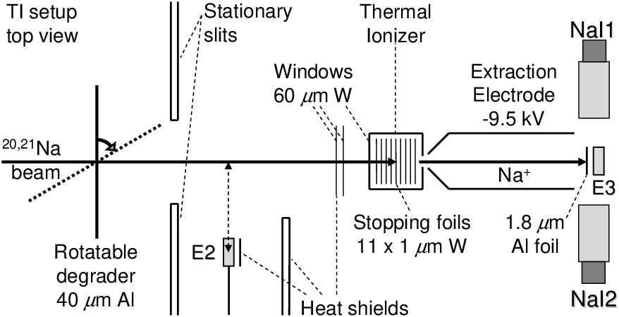
The isotopes employed for commissioning the thermal ionizer were 20Na ( 448 ms) and 21Na ( 22.5 s). The experimental setup is shown in Fig. 3. To allow varying of the implantation depth a rotatable 40 m Al degrader was used for fine adjustment of the energy of the incoming ions. A thin Si detector () upstream of the TI served for energy loss and time-of-flight measurements for identification and optimization of the incoming flux of secondary beam. A 1.8 m thick aluminium foil was placed in front of Si detector () in order to stop the ions extracted from the TI. was positioned behind the foil in order to measure the rate of delayed particles from the -decay of 20Na. The alpha lines and branching ratios are well known [27]. The rate of particles was measured in order to obtain the detection efficiency of a NaI detector pair measuring electron-positron annihilation photons. The latter was necessary for the detection of extracted 21Na ions where no delayed particles exist.

The rate of the extracted 20Na ions was measured for different ionizer temperatures (Fig. 4). 20Na lines were detected first at 2100 ∘C. The rate of 20Na is increased by approximately 25 times at 2470 ∘C due to decreased diffusion delay and increased ionization efficiency. The 20Na relative efficiency is plotted in Fig. 4 together with data for 21Na at 2350 ∘C. We have measured at most 48(3) efficiency for 21Na with the current setup. The efficiency difference for 20Na and 21Na is explained by the lifetimes of the isotopes in combination with the diffusion-related delay in the TI. The data allows to estimate the diffusion constant for sodium in tungsten to be at most m2/s at 2350 ∘C.
The slowed radioactive ion beams were transported to the trapping chamber. The beam line includes a radio frequency quadrupole (RFQ) cooler/buncher system and a drift tube system in the low energy beam line (LEBL).
4 Outlook
A thermal ionizer has been designed, built and commissioned as an ion catcher for the TRIP facility. Design modifications were recently made in order to provide stable long term operation at temperatures above 2500 ∘C. The main modification utilizes a new design for the support of the filaments. The efficiencies are expected to be significantly increased at higher temperatures due to shorter diffusion times in 0.75 m thick foils and the increasing significance of the hot cavity effect. Other design modifications include changes in the design of the extraction aperture which will allow to achieve better transmission to the following stages of the low energy beam line of the TRIP facility.
The next experimental steps will include neutralization of radioactive ions for laser trapping in a magneto-optical trap (MOT). From the present data and the observation in [5] it can be concluded that a TI is a more efficient ion catcher than current gas stoppers for an in-flight production of Na isotopes with high intensities. A thermal ionizer is expected to be suitable also for slowing of other chemically similar elements.
References
- [1] E. Traykov , U. Dammalapati, S. De, O.C. Dermois, L. Huisman, K. Jungmann, W. Kruithof, A.J. Mol, C.J.G. Onderwater, A. Rogachevskiy, M. da Silva e Silva, M. Sohani, O. Versolato, L. Willmann, H.W. Wilschut, Nucl. Instr. and Meth. B, this volume.
- [2] E. Traykov, A. Rogachevskiy, M. Bosswell, U. Dammalapati, P. Dendooven, O.C. Dermois, K. Jungmann, C.J.G. Onderwater, M. Sohani, L. Willmann, H.W. Wilschut, A.R. Young, Nucl. Instr. and Meth. A 572 (2007) 580.
- [3] G.P.A. Berg, O.C. Dermois, U. Dammalapati, P. Dendooven M.N. Harakeh, K. Jungmann, C.J.G. Onderwater, A. Rogachevskiy, M. Sohani, E. Traykov, L.Willmann, H.W. Wilschut, Nucl. Instr. and Meth. A 560 (2006) 169.
- [4] J. Ärje, J. Äystö, H. Hyvönen, P. Taskinen, V. Koponen, J. Honkanen, A. Hautojärvi, K. Vierinen, Phys. Rev. Lett. 54 (1985) 99.
- [5] M. Huyse, Nucl. Phys. A 187 (2002) 265c.
- [6] L. Willmann, G.P. Berg, U. Dammalapati, S. De, P. Dendooven, O. Dermois, K. Jungmann, A. Mol, C.J.G. Onderwater, A. Rogachevskiy, M. Sohani, E. Traykov, H.W. Wilschut, AIP Conf. Proc., 821 (2006) 523.
- [7] P. Dendooven, S. Purushothaman, K. Gloos, Nucl. Instr. Meth. A 558 (2006) 580.
- [8] R. Kirchner, Nucl. Instr. and Meth. 186 (1981) 275.
- [9] H.W. Wilschut, M.N. Harakeh, R. Hoekstra, R. Morgenstern, TRIP project proposal, 1999.
- [10] K. Jungmann, Acta Phys. Pol. B 33 (2002) 2049.
- [11] H.W. Wilschut, Hyp. Interact. 146/147 (2003) 77.
- [12] K. Jungmann, Nucl. Phys. A 751 (2005) 87c.
- [13] J.F. Ziegler, J.P. Biersack, U. Littmark, The Stopping and Rangeof Ions in Solids, Pergamon, New York, 1985.
- [14] A. Fick, Ann. Phys. Lpz. 170 (1855) 59.
- [15] J. Crank, The Mathematics of Diffusion, 2nd ed., Clarendon, Oxford, 1979.
- [16] M. Fujioka, Y. Arai, Nucl. Instr. and Meth. 186 (1981) 409.
- [17] E. Traykov, Production of radioactive beams for atomic trapping, PhD thesis, KVI, University of Groningen, 2006.
- [18] G.M. McCracken, H.M. Love, Phys. Rev. Lett. 5 (1960) 201.
- [19] H.M. Love, G.M. McCracken, Canad. J. Phys. 41 (1963) 83.
- [20] B. Bayat, H.W. Wassmuth, Surf. Sci. 133 (1983) 1.
- [21] R. Kirchner, Nucl. Instr. and Meth. B 70 (1992) 186.
- [22] H. Rossbach, B. Eichler, Report ZfK 527 (1984) 1.
- [23] I. Langmuir, K.H. Kingdon, Proc. Royal Soc. A 107 (1925) 61.
- [24] S. Datz, E. Taylor, J. Chem. Phys. 25 (1956) 389.
- [25] R. Kirchner, Nucl. Instr. and Meth. A 292 (1990) 203.
- [26] O.C. Dermois, L. Huisman, K. Jungmann, L. Slatius, E.K. Traykov, H.W. Wilschut, KVI Annual Report, (2005) 15.
- [27] E.T.H. Clifford, E. Hagberg, J.C. Hardy, H. Schmeing, R.E. Azuma, H.C. Evans, V.T. Koslowsky, U.J. Schrewe, K.S. Sharma, I.S. Towner, Nucl. Phys. A 493 (1989) 293.