Slow wave resonance in periodic stacks of anisotropic layers
Abstract
We consider a Fabry-Perot resonance (a transmission band edge resonance) in periodic layered structures involving birefringent layers. In our previous publication [2] we have shown that the presence of birefringent layers with misaligned in-plane anisotropy can dramatically enhance the performance of the photonic-crystal resonator. It allows to reduce its size by an order of magnitude without compromising on its performance. The key characteristic of the enhanced slow-wave resonator is that the Bloch dispersion relation of the periodic structure displays a degenerate photonic band edge, in the vicinity of which the dispersion curve can be approximated as , rather than . Such a situation can be realized in specially arranged stacks of misaligned anisotropic layers. On the down side, the presence of birefringent layers results in the slow wave resonance being coupled only with one (elliptic) polarization component of the incident wave, while the other polarization component is reflected back to space. In this paper we show how a small modification of the periodic layered array can solve the above fundamental problem and provide a perfect impedance match regardless of the incident wave polarization, while preserving the giant slow-wave resonance characteristic of a degenerate photonic band edge. Both features are of critical importance for many practical applications, such as the enhancement of various light-matter interactions, light amplification and lasing, optical and microwave filters, antennas, etc.
1 Introduction
Wave propagation in spatially periodic media, such as photonic crystals, can be qualitatively different from any uniform substance. The differences are particularly pronounced when the wavelength is comparable to the primitive translation of the periodic structure [3, 4, 5, 6, 7, 8, 9]. The effects of strong spatial dispersion culminate at stationary points of the Bloch dispersion relation where the group velocity of a traveling Bloch wave vanishes
| (1) |
One reason for this is that vanishing group velocity always implies a dramatic increase in density of modes at the respective frequency. In addition, vanishing group velocity also implies certain qualitative changes in the eigenmode structure, which can be accompanied by some spectacular effects in wave propagation. A particular example of the kind is the frozen mode regime associated with a dramatic amplitude enhancement of the wave transmitted to the periodic medium [10, 11, 12, 13, 14, 15]. In this paper, we focus on a different slow-wave effect, namely, on a Fabry-Perot resonance in bounded photonic crystals. This slow wave phenomenon, illustrated in Figs. 1 and 2, is also referred to as the transmission band edge resonance. There are some similarities between the frozen mode regime and the slow-wave resonance in plane-parallel photonic crystals. Both effects are associated with vanishing group velocity at stationary point (1) of the Bloch dispersion relation. As a consequence, both effects are strongly dependent on specific type of spectral singularity (1). A fundamental difference though is that the frozen mode regime is not a resonance phenomenon in a sense that it is not particularly sensitive to the shape and size of the photonic crystal. For instance, the frozen mode regime can occur even in a semi-infinite periodic structure, where the incident plane wave is converted to a frozen mode slowly propagating through the periodic medium until it is absorbed [10, 11, 12, 13, 14, 15]. By contrast, in the case of a slow wave resonance, the entire bounded periodic structure acts as a resonator, resulting in a strong sensitivity of the resonance behavior to the size and shape of the photonic crystal.
It is also important to distinguish between two qualitatively different classes of photonic-crystal resonators. The first class comprises resonance cavities where the role of periodic dielectric structure reduces to electromagnetic (EM) field confinement by reflecting it back to the cavity interior. The resonance frequency (or frequencies) of such photonic cavities usually lies in a frequency gap (a stop-band) of the photonic crystal. The periodic dielectric array here plays the role of a distributed Bragg reflector. The number of resonance modes depends on the cavity size. It can be a single mode localized on an isolated defect inside the photonic crystal [17, 18]. Or the cavity can support multiple resonances, if its size significantly exceeds the light wavelength. More detailed information on photonic crystal cavities can be found in numerous papers and monographs on optics and photonics (see, for example, [19] and references therein). In this paper, we will not further discuss this subject.
The second class of photonic-crystal resonators comprises the, so-called, slow-wave resonators. They are qualitatively different from the band-gap cavities. In slow-wave photonic-crystal resonators, the reflectors may not be needed at all, as shown in the example in Fig. 1. The role of the periodic structure here is to support slow EM waves. The resonance frequencies lie in the transmission bands of the photonic crystal – not in band gaps. Although, the resonance frequencies can be very close to a band edge (1), as shown in Fig. 2. A typical example of slow wave resonance in a photonic crystal is presented by the transmission band edge resonance, illustrated in Figs. 1 and 2. In certain cases, slow-wave resonators can provide significant advantages over cavity resonators. They are used for the enhancement of light-matter interactions, such as nonlinear and nonreciprocal effects, optical activity, light amplification and lasing, etc. They can also be used in optical and microwave filters, delay lines, as well as for the enhancement of antenna gain and directionality. More detailed information can be found in an extensive literature on the subject (see, for example, [20, 6, 7, 8, 21, 22, 23, 24, 25], and references therein).
In this paper we describe a slow-wave photonic-crystal resonator with drastically reduced dimensions and enhanced performance, compared to that of a common Fabry-Perot resonator based on a periodic stack of non-birefringent layers. The idea is to employ periodic structures supporting the dispersion relations different from those allowed in periodic arrays of non-birefringent layers. Indeed, periodic arrays involving birefringent layers can display stationary points (1) different from a regular photonic band edge in Fig. 2(a). Some examples are shown in Fig. 3. Slow waves associated with such stationary points can produce giant transmission band-edge resonances, much more powerful compared to those achievable in common layered structures. The first step in this direction was made in [2], where it was shown that the transmission band-edge resonance in the vicinity of a degenerate photonic band edge (DBE) in Fig. 3(b) produces much better results, compared to a regular photonic band edge (RBE) of Figs. 2(a) and 3(a). Specifically, at the frequency of DBE related giant slow-wave resonance, the electromagnetic energy density inside the photonic-crystal can be estimated as
| (2) |
where is the energy density of the incident wave and is the total number of unit cells in the periodic stack. By comparison, the average EM energy density at a regular transmission band-edge resonance in Fig. 2 is
| (3) |
The estimations (2) and (3) imply that the Q-factor of a DBE based slow-wave resonator can be by factor higher compared to that of a RBE related Fabry-Perot resonator of the same size. And this a huge difference! A detailed comparative analysis of the giant DBE related slow wave resonance versus the regular transmission band edge resonance can be found in [2].
On the down side, periodic structures with birefringent layers have a fundamental problem – their reflectance and transmittance are essentially dependent on the incident wave polarization. This dependence is particularly strong near the edges of transmission bands, where the slow-wave resonances occur. In particular, a DBE related giant transmission resonance described in [2] is coupled only with one (elliptic) polarization component of the incident wave, while the other polarization component is reflected back to space by the photonic crystal boundary [2]. In other words, at the resonance frequency, a periodic stack involving birefringent layers acts as a polarizer, reflecting back to space roughly half of the incident wave energy. This behavior is illustrated in Figs. 4 and 5. Similar problem exists in all different modifications of the frozen mode regime considered in [10, 11, 12, 13, 14, 15]. For many applications, such a polarization selectivity may not be acceptable. In this paper we offer a solution to the above problem. We show how to utilize all the incident wave energy, while preserving the extraordinary performance of the DBE based photonic-crystal resonator. The idea is to modify the periodic layered array so that instead of a degenerate band edge, the respective dispersion curve develops a split photonic band edge (SBE) shown in Fig. 3(b). Under certain conditions specified below, the photonic resonator with a SBE will display a giant transmission band edge resonance, similar to that of a DBE. But, in addition, the SBE resonator couples with the incident wave regardless of its polarization and, therefore, utilizes all the incident EM radiation – not just one polarization component. The latter feature is of critical importance for a variety of practical applications.
2 Dispersion relation and energy flux in periodic arrays of birefringent layers
In this section we introduce some basic definitions and notations of electrodynamics of stratified media composed of birefringent layers. A detailed and consistent description of the subject, along with numerous references, can be found in [2, 10, 11, 15], where similar notations and terminology are used. For simplicity, we restrict ourselves to the case of a plane monochromatic wave normally incident on a layered structure, as shown in Fig. 1. The results can be easily generalized to the case of oblique incidence, as it was done, for example, in [11, 15].
2.1 Transverse waves in stratified media
Time-harmonic electromagnetic field inside and outside the layered medium can be described by the vector-column
| (4) |
where and are time-harmonic electric and magnetic fields. The direction is normal to the layers. The values of at any two different locations and are related by the transfer matrix defined by
| (5) |
The elements of the transfer matrix are expressed in terms of material tensors and other physical characteristics of the stratified medium.
Let , , and be the incident, reflected, and transmitted waves, respectively, as shown in Fig. 1 . To the left of the stack (at ), the electromagnetic field is a superposition of the incident and reflected waves. To the right of the stack (at ), there is only the transmitted wave. The field inside the periodic medium is denoted as . Since all four transverse field components in (4) are continuous functions of , we have the following boundary conditions at and in Fig. 1
| (6) |
| (7) |
2.2 Time-harmonic field inside periodic layered structure
At any given frequency , the time-harmonic field inside the periodic stratified medium can be represented as a superposition of Bloch eigenmodes, each of which satisfies the following relation
| (8) |
or, equivalently,
| (9) |
The Bloch wave number is defined up to a multiple of . The correspondence between and is referred to as the Bloch dispersion relation. Real correspond to propagating (traveling) Bloch modes. Propagating modes belong to different spectral branches separated by frequency gaps. In reciprocal and/or centrosymmetric periodic structures, the Bloch dispersion relation is always symmetric with respect to the points and of the Brillouin zone
| (10) |
where
| (11) |
In periodic structures composed of non-birefringent layers, every Bloch wave is doubly degenerate with respect to polarization. Typical diagram for such a case is shown in Fig. 2(a). If, on the other hand, some of the layers display an in-plane anisotropy or gyrotropy, the polarization degeneracy can be lifted. The respective diagrams are shown in Fig. 3.
Finally, if some of the layers are magnetically polarized and, in addition, the periodic array is non-centrosymmetric, the dispersion relation can also develop spectral asymmetry
| (12) |
This effect can be significant if the magnetic layers display an appreciable nonreciprocal circular birefringence (magnetic Faraday rotation). Examples of periodic layered structures with asymmetric dispersion relation (12) can be found in [16, 10]. Further in this paper we only discuss non-magnetic structures.
The speed of a traveling wave in a periodic medium is determined by the group velocity . Normally, every spectral branch develops stationary points (1) where the group velocity of the corresponding propagating mode vanishes. Usually, such points are located at the center and at the boundary of the Brillouin zone
| (13) |
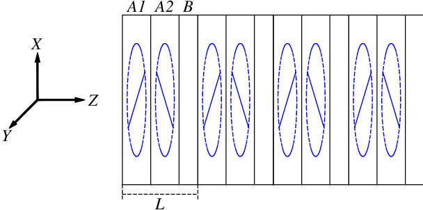
This is always the case in periodic layered structures composed of non-birefringent layers, where all stationary points coincide with photonic band edges, as shown in Fig. 2(a). If, on the other hand, some of the layers in a unit cell are birefringent, then in addition to (13), some dispersion curves can also develop a reciprocal pair of stationary points corresponding to a general value of the Bloch wave number , as shown in Fig. 3(b). The respective portion of the diagram can be described as a split band edge (SBE). The dispersion relation can develop a DBE or a SBE only if the periodic layered array has birefringent layers with misaligned in-plane anisotropy [2, 15]. Example of such a layered structure is shown in Fig. 6.
Unlike propagating modes, evanescent Bloch modes are characterized by complex wavenumbers . Under normal circumstances, evanescent modes decay exponentially with the distance from the periodic structure boundaries. In such cases, the evanescent contribution to can be significant only in close proximity of the surface or some other defects of the periodic structure. The situation can change dramatically in the vicinity of a stationary point (1) of the dispersion relation. At first sight, stationary points (1) relate only to propagating Bloch modes. But in fact, in the vicinity of every stationary point frequency , the imaginary part of the Bloch wavenumber of at least one of the evanescent modes also vanishes. As a consequence, the respective evanescent mode decays very slowly, and its role may extend far beyond the photonic crystal boundary. In addition, in some special cases, the electromagnetic field distribution in the coexisting propagating and/or evanescent eigenmodes becomes very similar, as approaches . This can result in a spectacular effect of coherent interference, such as the frozen mode regime [10, 11, 14, 15]. What exactly happens in the vicinity of a particular stationary point essentially depends on its character and appears to be very different for different types of singularity (1).
Using the transfer matrix (5), the Bloch relation (8) can be recast as
| (14) |
where is the transfer matrix of a unit cell
At any given frequency, there are four Bloch eigenmodes, propagating and/or evanescent, with different polarizations and wave numbers
| (15) |
Depending on the frequency , the full set (25) of Bloch eigenmodes may include only propagating modes, only evanescent modes, or both. In any event, the respective set of four Bloch wave numbers satisfies the relation
| (16) |
which is a direct consequence of unitarity of the transfer matrix (see [15] and references therein).
Taking into account (16), one can distinguish the following three possibilities.
- 1.
All four Bloch modes in (25) are propagating
(17) In this case, two of the propagating modes have positive group velocities, they are referred to as forward waves. The other two Bloch waves have negative group velocities, they are referred to as backward waves.
- 2.
All four Bloch modes in (25) are evanescent
(18) This is the case when the frequency falls into a photonic band gap. According to (16), one can assume that
(19) Two of the evanescent modes have ; they are referred to as forward evanescent modes. The other two evanescent modes have ; they are referred to as backward evanescent modes.
- 3.
In all cases, propagating modes with and evanescent modes with are referred to as forward waves. The propagating modes with and evanescent modes with are referred to as backward waves.
2.3 EM energy flux in layered media
The real-valued energy flux (the Poynting vector) associated with time-harmonic field (4) is
| (22) |
The expression (22) can also be recast in the following compact form [14]
| (23) |
where
| (24) |
2.3.1 EM energy flux in layered media
In the case of a lossless stratified medium, the Poynting vector in (23) is independent of the coordinate .
In a periodic layered medium, the column vector in (23) can be represented as a linear combination of four Bloch components (25)
| (25) |
Substituting (25) into (23) yields
| (26) |
At this point we can apply the orthogonality relation
| (27) |
the proof of which can be found in [14], P. 327. The expression (26) together with (27) lead to the following conclusions regarding the energy flux of a time-harmonic electromagnetic field in lossless periodic layered media.
- 1)
The contribution of each propagating Bloch mode to the total energy flux is independent of the presence or absence of other Bloch eigenmodes with the same frequency
(28) where the summation runs over all propagating eigenmodes. The number of propagating modes can be 4, 2, or 0, depending on which of the cases (17), (20), or (18) we are dealing with.
- 2)
The contribution of evanescent eigenmodes to the energy flux depends on how many of them exist at this particular frequency .
- (a)
In the case (20) of two evanescent modes and we have
(29) which implies that only a pair of evanescent modes with conjugate wave numbers can contribute to the energy flux. The respective contribution (29) is independent of the presence of propagating modes and . In accordance with Eq. (29), a single evanescent mode, either or , does not produce energy flux on its own.
- (b)
In the case (18) of four evanescent modes we have
(30) which implies that either of the two pairs of evanescent modes with conjugate wave numbers contribute to the energy flux independently of each other.
- (a)
In the general case of the time-harmonic EM field being a superposition (25) of several Bloch modes, propagating and evanescent, the contribution of each propagating mode to the total energy flux can be expressed in terms of its group velocity and amplitude
| (31) |
where
| (32) |
In the particular case of a single propagating mode, the quantity in (31) is equal to the energy density averaged over a unit cell .
2.3.2 Transmission/reflection coefficients
Let , , , and be the energy fluxes of the respective waves in Fig. 1. The transmission/reflection coefficients and are defined as
| (33) |
In the case of losses medium, the Poynting vector is independent of
In such a case
| (34) |
Otherwise,
where is the absorption coefficient of the stack.
2.4 Single mode excitation regime
To explain the nature of strong polarization dependence of the transmission band edge resonance in periodic stacks of anisotropic layers we introduce some basic concepts related to semi-infinite periodic layered structures. Then, we will see how those concepts apply to finite periodic stacks.
Consider a plane monochromatic wave incident on a semi-infinite periodic structure with the same unite cell as that of the finite periodic stack in Fig. 1. In other words, let us assume that the right-hand boundary of the photonic crystal in Fig. 1 is absent. In such a case, the EM field inside the periodic medium is a superposition of two forward Bloch waves, each of which can be either propagating with , or evanescent with . The backward Bloch modes (propagating with and evanescent with ) do not contribute to in the case of a semi-infinite periodic structure. According to [15], the incident wave polarization can always be chosen so that only one of the two forward Bloch waves is excited. Such a situation is referred to as a single mode excitation regime. The respective two polarizations of the incident wave are referred to as the single mode excitation polarizations. In periodic structures involving birefringent layers, a single mode excitation polarization is, generally, elliptic. Note, that if all the layers are non-birefringent, then, due to polarization degeneracy, the very concept of a single mode excitation regime at normal propagation makes no sense. In the case of oblique incidence, though, a single mode excitation regime exists even in periodic structures composed of non-birefringent layers; the respective incident wave polarizations are linear and referred to as TE and TM.
As we already mentioned, the dispersion relation of a periodic structure involving birefringent layers usually does not display polarization degeneracy. In particular, the periodic stack in Fig. 6 can display polarization degeneracy at normal propagation only if the misalignment angle (87) between the adjacent anisotropic layers and is . In all numerical examples in this paper, the misalignment angle is different from and , because otherwise the existence of a DBE and a SBE would be ruled out by symmetry [15]. Therefore, none of the spectral branches in Fig. 3 is degenerate with respect to polarization.
2.4.1 The vicinity of a RBE
Consider the vicinity of a RBE or in Fig. 3(a). If the incident wave frequency lies in a transmission band close enough to the respective RBE, the transmitted wave inside the semi-infinite periodic layered structure is a superposition of two forward Bloch waves
| (35) |
one of which is propagating and the other is evanescent. There are two single mode excitation regimes at such a frequency. The first one produces only propagating mode at , while the other produces only evanescent mode at . The respective transmission coefficients satisfy the following relations
| (36) |
| (37) |
Eq. (37) reflects the fact that according to (29), a single evanescent mode does not contribute to the energy flux.
The relations (36) and (37) imply that only one of the two polarization components of the incident wave (the one producing the forward propagating mode ) can be transmitted to the semi-infinite photonic crystal. The other polarization component of the incident wave (the one producing only evanescent mode ) will be totally reflected back to space.
Now, what happens if the periodic structure has a finite thickness? In such a case, the relation (35) does not apply. Instead, the EM field inside the finite periodic stack is a superposition of all four Bloch waves (25), including both forward and backward modes. If the number of unit cells in the periodic stack is significant, then at certain frequencies, the pair of propagating modes (one forward and one backward ) form a standing wave (40) constituting the transmission band edge resonance. An important point, though, is that such a resonance is excited only by one (elliptic) polarization component of the incident wave – the same component that produces a single propagating mode inside the semi-infinite structure. If, on the other hand, the incident wave polarization is such that it produces a single evanescent mode inside the semi-infinite structure, then it will be reflected back to space from the finite periodic stack as well. In practice, the relation (37) is valid even for the finite periodic structures composed of as few as several unit cells .
2.4.2 The vicinity of a DBE
Consider now the vicinity of a DBE in Fig. 3(b). If the incident wave frequency lies in the upper transmission band close to the DBE , the transmitted wave inside the semi-infinite periodic layered structure still is a superposition (35) of one propagating and one evanescent Bloch waves. But remarkably, in close proximity of the DBE, the column vectors and in (35) become nearly parallel to each other, while their amplitude diverges [15]. More specifically, at the photonic crystal boundary at
| (38) |
provided that the incident wave has some general polarization and fixed amplitude. The destructive interference (38) ensures that the boundary condition (6) can be satisfied, while both Bloch contributions to diverge. As the distance from the slab boundary increases, the evanescent component dies out
| (39) |
while the propagating component remains constant and very large. Eventually, as the distance further increases, the transmitted wave reaches its large saturation value corresponding to its propagating component . This constitutes the DBE related frozen mode regime in a semi-infinite photonic crystal [15].
Generally, the incident wave polarization can always be chosen so that only one of the two forward Bloch waves in (35) is excited in the semi-infinite photonic crystal (a single mode excitation regime). What happens to the frozen mode regime in such a case? Obviously, the destructive interference (38) cannot occur in a single mode excitation regime. As a consequence, the incident wave is reflected back to space without producing the frozen mode, regardless of whether the single mode excitation regime produces a single propagating or a single evanescent Bloch mode [15]. The latter circumstance is related to the fact that the incident wave polarizations producing a single propagating mode and a single evanescent mode become indistinguishable as .
The fact that all four Bloch modes (25) are nearly parallel to each other in the vicinity of a DBE is also very important for understanding the DBE related giant transmission band edge resonance in a finite photonic crystal. Indeed, as we pointed out earlier, in the case of RBE related resonance, the incident wave producing a single propagating mode is coupled with the resonance mode, while the incident wave producing a single evanescent mode is not. By contrast, in the case of DBE related resonance, both polarizations are nearly indistinguishable. As a result, neither of the two single mode regime polarizations is coupled with the resonance mode. Instead, the best result is achieved if the incident wave polarization is orthogonal to that of single mode regime polarization. A numerical illustration of this point is given in Fig. 4.
In summary, the DBE related transmission band edge resonance is not excited if the incident wave polarization corresponds to the single mode excitation regime. This implies that if the incident wave polarization is randomly chosen, then on average, at least half of the incident wave energy is reflected back to space from the photonic crystal boundary, without contributing to the resonance. The above problem can be overcome in slightly modified periodic structures displaying a SBE, rather than a DBE.
3 Simplified geometrical description of transmission band-edge resonance
Steady-state Fabry-Perot resonance in a pane-parallel photonic crystal is commonly described as a standing wave composed of a pair of reciprocal propagating Bloch waves (40) with equal and opposite Bloch wave numbers and vanishing group velocities. The nodes of the standing wave coincide with the photonic crystal boundaries at and . This simple representation works very well in the vicinity of a regular photonic band edge (RBE). But, in the cases of DBE or SBE related giant transmission band edge resonance, the above simple picture should be significantly modified. We start this section with a brief description of the standing wave concept as applied to a regular transmission band edge resonance. Then we proceed to a comparative analysis of giant transmission band edge resonances in the vicinity of a DBE and SBE.
3.1 Slow-wave resonance as a standing wave
Consider a finite plane-parallel periodic structure composed of unit cells . If the number is significant, the electromagnetic properties of the periodic stack can be effectively described in terms of the Bloch eigenmodes (9) of the corresponding infinite periodic layered medium. For instance, a periodic stack having as few as several periods can display almost total reflectivity at photonic band gap frequencies, which results from the absence of propagating Bloch modes at the respective frequency range. A typical dependence of the finite stack transmittance on the incident wave frequency is shown in Fig. 2(b). The sharp peaks in transmission bands correspond to transmission band edge resonances. The resonance frequencies are located close to a photonic band edge, where the group velocity is very low. At each resonance, the electromagnetic field inside the periodic stack is close to a standing wave composed of a pair of reciprocal Bloch waves with large and nearly equal amplitudes and low group velocity
| (40) |
where
The photonic crystal boundaries at and coincide with the standing wave nodes, where the forward and backward Bloch components interfere destructively to meet the boundary conditions (6) and (7). The latter circumstance determines the wave numbers of the Bloch eigenmodes contributing to the resonance field inside the periodic structure
| (41) |
The wave number is given in (11). The integer denotes the resonance peaks in order of their distance from the respective photonic band edge. The respective resonance frequencies are expressed in terms of the dispersion relation
| (42) |
According to (41), the proximity of the resonances to the photonic band edge is determined by the number of unit cells in the periodic stack. The expressions (41) and (42) only apply if
| (43) |
Let us introduce the following dimensionless notations for the small deviation of the wave number and the frequency from the respective stationary point
| (44) |
According to (41) and (42), the resonance values of and are
| (45) |
The most powerful resonance is usually the one closest to the respective photonic band edge
| (46) |
3.2 Energy density and energy flux at resonance frequency
Assume that the amplitude of the incident wave in Fig. 1 is unity. Due to the boundary condition (6), we have at the left-hand boundary of the photonic crystal in Fig. 1
| (47) |
At resonance frequency, the transmission coefficient (34) is close to unity
| (48) |
Therefore, the relation similar to (47) also applies at the right-hand boundary of the periodic stack
| (49) |
Let us see under what conditions the finite resonance transmission (48) is compatible with the vanishing group velocity in the vicinity of stationary point (1), where the transmission band edge resonance occurs. According to (31), the energy flux associated with the time-harmonic field in (40) is
| (50) |
where
| (51) |
and
In the vicinity of stationary point (1), the magnitude of the group velocity in (50) is vanishingly small. The fact that the resonance energy flux remains of the order of unity implies that the amplitude of the Bloch components in (50) increases so that
| (52) |
or, equivalently,
| (53) |
Thus, finite transmittance at requires the divergence (53) of the amplitude of the Bloch components.
The requirements (47) and (49) together with (53) imply that although the amplitudes of the forward and backward Bloch components both diverge as , they must interfere destructively near the photonic crystal boundaries
and
In order to reconcile the boundary condition (47) with the requirement (53) of a finite energy flux, we have to impose the following requirement on the amplitudes of the two Bloch components
| (54) |
The relation (54) was derived under the assumption that the time-harmonic filed inside the periodic medium is a superposition (40) of one forward and one backward propagating Bloch waves with equal and opposite wave numbers and group velocities. This assumption is warranted in the vicinity of a regular photonic band edge of a periodic stack with birefringent layers, such as those shown in Fig. 3(a). In a periodic stack of non-birefringent layers, at any given frequency there are two pairs of reciprocal Bloch waves with equal wave numbers but different polarizations. Still, because of the polarization degeneracy, the above consideration can be directly applied to the latter case, as well.
By contrast, in the DBE and SBE related transmission band edge resonances, the contribution of all four Bloch components to the resonance field is absolutely essential. In such cases, the treatment of the transmission band edge resonance as a simple standing wave (50) is not adequate.
3.3 Regular photonic band edge (RBE)
Let us apply the relation (54) to the classical case of Fabry-Perot resonance in the vicinity of a regular photonic band edge (RBE). Using the notations (44), the dispersion relation in the vicinity of a RBE can be approximated as
| (55) |
The group velocity magnitude is
| (56) |
According to (45), the resonance values of the wave number and the frequency are, respectively
The group velocity magnitude at resonance is
| (57) |
Substitution of to (54) yields
The energy density distribution at RBE related resonances is typical of a standing wave
| (58) |
In the case of the most powerful first transmission resonance ( the one with ), the two Bloch components in (40) interfere constructively in the middle of the periodic structure. The respective field intensity is
| (59) |
3.4 Degenerate photonic band edge (DBE)
The dispersion relation in the vicinity of a DBE in Fig. 3(b) can be approximated as
| (60) |
The magnitude of the group velocity of each of the reciprocal pair of propagating modes is
| (61) |
Unlike the case of RBE related resonance, in the vicinity of a DBE, the EM field inside the periodic medium cannot be approximated by a simple standing wave (40). Instead, we have to take into account the evanescent mode contribution, which appears to be comparable to that of the propagating modes [2]. As the result, the simple geometrical conditions (41) and (45) give only rough order of magnitude estimate of the resonance values of the wave number and frequency. More importantly, the maximum field intensity inside the photonic crystal at the frequency of the transmission band-edge resonance is now
| (62) |
which is by factor larger than that of a regular transmission resonance given in (59).
The detailed analysis of the DBE related giant transmission resonance was carried out in [2]. Here, we would like to highlight the down side of this effect, which is the polarization selectivity illustrated in Figs. 4 and 5. As we already stated before, the DBE related giant transmission resonance is coupled only with one (elliptic) polarization component of the incident wave, while the other polarization component is reflected back to space by the photonic crystal boundary. The reflected polarization component corresponds to the single mode excitation regime, explained at the end of Section 2. A solution to this fundamental problem is to slightly modify the periodic structure so that instead of a DBE, the respective spectral branch displays a SBE. Example of a SBE is shown in Fig. 3(b).
4 Transmission band-edge resonance in the vicinity of a split photonic band edge (SBE)
4.1 Simplified description of SBE related resonance
In the previous section we described the resonance conditions for a single pair (40) of reciprocal Bloch waves. In periodic stacks involving birefringent layers, a slow-wave resonance produced by a single pair of reciprocal Bloch waves can be excited by only one polarization component of the incident plane wave. The other polarization component is not coupled with the respective resonance mode. This implies that if the incident wave polarization is random, at least half of the incident wave energy will not enter the periodic medium and will be reflected back to space by the photonic crystal boundary.
Consider now the vicinity of a split photonic band edge (SBE) on the diagram in Fig. 3(b). The physical characteristics of the periodic structure are chose so that the SBE in Fig. 3(b) is close to a DBE. The frequency range
| (63) |
covers a narrow portion of the transmission band which includes the SBE. At any given frequency from (63), there are two pairs of reciprocal Bloch waves with very low group velocity and different polarizations; each pair being capable of producing its own slow-wave cavity resonance with the resonance conditions similar to (41) or (45). Our focus is on the possibility of the two resonances occurring at the same frequency. Such a situation will be referred to as the double resonance. It turns out that the double transmission band edge resonance is as powerful as the giant resonance associated with a DBE. But, in addition, a SBE related resonance utilizes all the energy of the incident wave regardless of its polarization. By contrast, a DBE based giant transmission resonance is coupled only with one polarization component of the incident wave; the rest of the incident wave energy being reflected back to space. This important difference is obvious if we compare the DBE related transmission dispersion shown Fig. 4 and the SBE related transmission dispersion shown in Fig. 7.
To start with, let us consider the dispersion curve with a SBE in more detail. If the split between the twin band edges and in Figs. 3(b) is small, the dispersion relation in the vicinity of SBE can be approximated as
| (64) |
where
| (65) |
and
| (66) |
The inequality (65) is the condition for SBE. Indeed, in the opposite case of
| (67) |
the dispersion curve (64) would develop a RBE at , as shown in Fig. 3(a). While in the case
| (68) |
the dispersion curve (64) would have a DBE at . The additional inequality (66) is the condition for the proximity of the SBE to a DBE. This proximity allows us to use the expansion (64) in the frequency range spanning both twin edges of the SBE. More importantly, the condition (66) is essential for the phenomenon of the giant transmission resonance in the vicinity of SBE.
There are three stationary points associated with a SBE. The first one is trivial
| (69) |
It is located either at the center of the Brillouin zone, or at its boundary. The other two stationary points correspond to the actual SBE
| (70) |
Taking into account (70), the condition (66) for the proximity of the SBE to a DBE can be recast as
| (71) |
The condition (71) implies that the points and on the dispersion curve are close to each other.
In what follows, we assume for simplicity that
| (72) |
In this case, the SBE in question corresponds to the upper edge of the transmission band, as shown in Fig. 4(b). The alternative case of
| (73) |
corresponds to the SBE being the lower edge of the respective transmission band. There is no qualitative difference between the two cases.
At any given frequency within the range
| (74) |
there are two pairs of reciprocal Bloch waves. Each pair comprises one forward and one backward propagating modes with equal and opposite wave numbers and group velocities
| (75) |
| (76) |
The pair of wave numbers (75) corresponds to the concave portion of the dispersion curve (64), while the pair of wave numbers (76) corresponds to the convex portion of the dispersion curve. Obviously,
| (77) |
At any given frequency, the EM field inside the periodic stack is
| (78) |
where
| (79) |
and
| (80) |
To distinguish between and , we will refer to the respective quantities as the external and internal. The inequality (77) justifies these terms.
4.2 Conditions for the double SBE resonance
Within the frequency range (74), either pair of the reciprocal Bloch waves (79) and (80) can develop a transmission resonance. Of particular interest here is the case where the two resonances occurs at the same or almost the same frequency. This situation is illustrated in Fig. 9(c), as well as in Fig. 7, and 8.
Let us start with the internal resonance created by the reciprocal pair (79) of Bloch waves corresponding to the concave section of the dispersion curve. It is possible that the frequency range (74) contains only a single cavity resonance – the one with . Such a case is determined by either the proximity of the SBE to a DBE, or by the right choice of the number of the unit cells in the stack. According to (70) and (41), the condition for a single internal resonance is
| (81) |
The respective resonance frequency is determined by (42) and (64)
| (82) |
where .
Consider now the external resonance created by the reciprocal pair (80) of Bloch waves corresponding to the convex section of the dispersion curve. Let us impose the condition
| (83) |
that the external and internal resonances occur at the same frequency (82). This condition leads to the following equality
Simple analysis shows that it is only possible if at we have
The relation
together with (75) and (76) yield
The frequency of the double transmission resonance is
| (84) |
The group velocities of the two reciprocal pairs of Bloch waves at the resonance frequency are
and
By comparison, in the case of a DBE related giant transmission band edge resonance, we would have the following estimation for the resonance frequency and the respective group velocity of the two Bloch components
These estimations are similar those related to the double transmission resonance associated with SBE. In either case, the average resonance energy density is estimated by (3), which justifies the term giant transmission resonance.
Let us remark that the entire consideration of this subsection was based on the assumption that each pair (79) and (80) of the reciprocal Bloch waves is responsible for its own individual transmission resonance, described as a standing wave (79) or (80), respectively. While the double resonance at is described as the situation where the frequencies and of those individual resonances merely coincide. In fact, these two transmission resonances can be treated as independent only if the respective resonance frequencies and are well separated. As soon as and are close to each other, the EM field in (78) becomes a superposition of all four propagating Bloch modes. The latter situation persists even if the incident wave polarization correspond to the, so-called, single mode excitation regime, defined in the previous section. In other words, the single mode excitation regime produces almost pure internal or external resonance, provided that their frequencies are well separated. Otherwise, the EM field is a superposition of all four Bloch eigenmodes with two essentially different sets of wave numbers. In such a case, the resonance field cannot be viewed as a standing wave (40). The physical reason for such a strong hybridization is that due to the condition (71), the RBE in question is very close to a DBE. On the other hand, in the vicinity of a DBE, all four vector-columns in (25) become nearly parallel to each other [2, 15]. The latter circumstance excludes the possibility of exciting only one of the two pairs of the reciprocal Bloch modes (79) or (80) in the situation (83), where the resonance conditions (41) are in place for both of them simultaneously. The strong hybridization implies that the estimation (84) of the double resonance frequency is rather crude. Still, it provides a very useful guidance on the conditions for SBE related giant transmission resonance. The bottom line is that the SBE related giant transmission resonance is as powerful as that related to a DBE. But, in addition, the SBE related resonance provides a perfect coupling with the incident wave regardless of its polarization.
5 Conclusion
In summary, we would like to stress that the remarkable features of the DBE and SBE related giant transmission resonances can be derived from such fundamental characteristics of the periodic composite medium as its electromagnetic dispersion relation. Specific details of the periodic array, such as physical characteristics of the constitutive components, or structural geometry, are only important as long as the symmetry of the periodic array is compatible with the existence of the required spectral singularities.
Acknowledgment and Disclaimer: Effort of A. Figotin and I. Vitebskiy is sponsored by the Air Force Office of Scientific Research, Air Force Materials Command, USAF, under grant number FA9550-04-1-0359. The authors are thankful to A. Chabanov for stimulating discussions.
References
- [1]
- [2] A. Figotin and I. Vitebskiy. Gigantic transmission band-edge resonance in periodic stacks of anisotropic layers. Phys. Rev. E72, 036619, (2005).
- [3] L. Brillouin. Wave Propagation and Group Velocity. (Academic, New York, 1960).
- [4] L. D. Landau, E. M. Lifshitz, L. P. Pitaevskii. Electrodynamics of continuous media. (Pergamon, N.Y. 1984).
- [5] J. Joannopoulos, R. Meade, and J. Winn. Photonic Crystals. (Princeton University Press, 1995).
- [6] A. Yariv and Pochi Yeh. Optical Waves in Crystals. (”A Wiley-Interscience publication”, 1984).
- [7] Pochi Yeh. ”Optical Waves in Layered Media”, (Wiley, New York, 1988).
- [8] Weng Cho Chew. ”Waves and Fields in Inhomogeneous Media”, (Van Nostrand Reinhold, New York, 1990).
- [9] M. Notomi. Theory of light propagation in strongly modulated photonic crystals: Refractionlike behavior in the vicinity of the photonic band gap. Phys. Rev. B62, 10696 (2000)
- [10] A. Figotin, and I. Vitebskiy. Electromagnetic unidirectionality in magnetic photonic crystals. Phys. Rev. B67, 165210 (2003).
- [11] A. Figotin, and I. Vitebskiy. Oblique frozen modes in layered media. Phys. Rev. E68, 036609 (2003).
- [12] J. Ballato, A. Ballato, A. Figotin, and I. Vitebskiy. Frozen light in periodic stacks of anisotropic layers. Phys. Rev. E71, (2005).
- [13] A. Figotin and I. Vitebskiy. Electromagnetic unidirectionality and frozen modes in magnetic photonic crystals. JMMM, 300, 117 (2006).
- [14] A. Figotin and I. Vitebskiy. Slow light in photonic crystals (Topical Review). Waves in Random Media, Vol. 16, No. 3, 293–382 (2006).
- [15] A. Figotin and I. Vitebskiy. Frozen light in photonic crystals with degenerate band edge. Phys. Rev. E74, 066613 (2006).
- [16] A. Figotin, and I. Vitebsky. Nonreciprocal magnetic photonic crystals. Phys. Rev. E63, 066609 (2001).
- [17] A. Figotin and V. Gorentsveig. Localized electromagnetic waves in a layered periodic dielectric medium with a defect. Phys. Rev. B58, 180 (1998).
- [18] A. Vinogradov, A. Dorofeenko, S. Erokhin, M. Inoue, A. Lisyansky, A. Merzlikin, and A. Granovsky. Surface state peculiarities in one-dimensional photonic crystal interfaces. Phys. Rev. E74, 045128 (2006).
- [19] M. Selim Unlu and S. Strite. Resonant cavity enhanced photonic devices. J. Appl. Phys. 78, 608 - 639 (1995).
- [20] J. Dowling, M. Scalora, M. Bloemer, and Ch. Bowden. The photonic band edge laser: A new approach to gain enhancement. J. Appl. Phys. 75, 1896 (1994).
- [21] M. Scalora, J. Flynn, S. B. Reinhardt, R. L. Fork, M. J. Bloemer, M. D. Tocci, C. M. Bowden, H. S. Ledbetter, J. M. Bendickson, J. P. Dowling, R. P. Leavitt. Ultrashort pulse propagation at the photonic band edge: Large tunable group delay with minimal distortion and loss. Phys. Rev. E54, #2, R1078 (1996).
- [22] M. Bloemer, Myneni, M. Centini, M. Scalora, and G. D’Aguanno. Transit time of optical pulses propagating through a finite length medium. Phys. Rev. E65, 056615 (2002).
- [23] M. Soljacic, S. Johnson, S. Fan, M. Ibanescu, E. Ippen, and J. D. Joannopoulos. Photonic-crystal slow-light enhancement of nonlinear phase sensitivity. J. Opt. Soc. Am. B., 19, #9, 2052 (2002).
- [24] J. Poon, J. Scheuer, Y. Xu, and A. Yariv. Designing coupled-resonator optical waveguide delay lines. J. Opt. Soc. Am. B, Vol. 21, No. 9 (2004).
- [25] S. Yarga, G. Mumcu, K. Sertel, J. Volakis. Degenerate Band Edge Crystals and Periodic Assemblies for Antenna Applications. Antenna Technology Small Antennas and Novel Metamaterials, 2006 IEEE IWAT, March 6-8, 2006 Page(s): 408 - 411.
6 Appendix
The simplest periodic layered structure supporting a DBE or a SBE at normal propagation is shown in Fig. 6. A unit cell contains one isotropic layer and two misaligned anisotropic layers and with inplane anisotropy. The isotropic layers have the thickness and the dielectric permittivity
| (85) |
The dielectric permittivity tensors in each anisotropic layer has the form
| (86) |
where the parameter characterizes the magnitude of inplane anisotropy, and the angle determines the orientation of the anisotropy axes in the plane. All the layers have the same thickness and the same magnitude of inplane anisotropy. The only difference between the adjacent anisotropic layers and in 6 is their orientation . An important characteristic of the periodic structure in Fig. 6 is the misalignment angle
| (87) |
between the layers and . This angle determines the symmetry of the periodic array and, eventually, the kind of diagram it can display.
In all numerical simulations related to the periodic layered structure in Fig. 6 we use the following values of the material parameters in (85), (86) and (87)
| (88) |
At normal propagation, the numerical value of in (86) is irrelevant. The relative thickness of the and layers, can be different in different examples.
In all plots of the field distribution inside periodic media at we, in fact, plotted the following physical quantity
| (89) |
which is the squared field amplitude averaged over a local unit cell. The actual function , as well as the electromagnetic energy density distribution , are strongly oscillating functions of the coordinate , with the period of oscillations coinciding with the unit cell length . Given the relation , the quantity (89) can also be qualitatively interpreted as the smoothed energy density distribution, with the correction coefficient of the order of unity.
In all plots, the distance the wave number , and the frequency are expressed in units of , , and , respectively.